27
Heatmaster
ss
G Series Furnace Operating Manual
Water Temp
Sensor
Yellow
–
1
Yellow
–
2
Red
–
3
Black
–
4
Blue - 5
O2 Sensor Board
O2 Sensor
+
-
120V AC
Input
+
-
-
24V DC
2.5A
Output
L N
6EP1332-5BA00
Cold
Start
1
2
3
4
5
Bottom Air
Damper Mode 3
1
2
3
4
5
Top Air
Damper Mode 3
Low Water
Cut-off
High Limit
_ +
Alarm
Light
L+ M-
L+ M-
U1 M1 I1
6ED1055-1MM00-0BA2
U2 M2
Load/
ByPass
Switch
N/O
COM
P
W
R
T-
O
U
T
C
O
M
N
E
G
S
E
N
E
X
C
RTD
Circuit Board
Li
ve
N
eu
tra
l
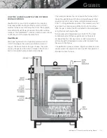
G-Series Wiring Diagram
G
ro
un
d
120V AC Power
Supply
Power Supply -120V 1PH 60 HZ
Max Breaker - 15 AMP
Running Load
–
2.5 Amps
Max Accessory Load
–
9.5 Amps
* Use Copper Conductors Only *
Revision 4.0
L+ M I1 I2 I3 I4 I5 I6
Q1
Q2
Q3
Q4
24V DC
Inputs
Outputs
6ED1052-1MD00-0BA8
I7 I8
L
Draft Fan
N
3
1
2
#1 Main Power Switch
#2 Control Panel Switch
#3 Breaker 2 Amp
Spring Wire
Connector
3
I2
Rear Electrical Box
6
–
24V +
7
–
24V -
8
–
0-10V DC
9 -
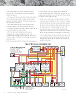
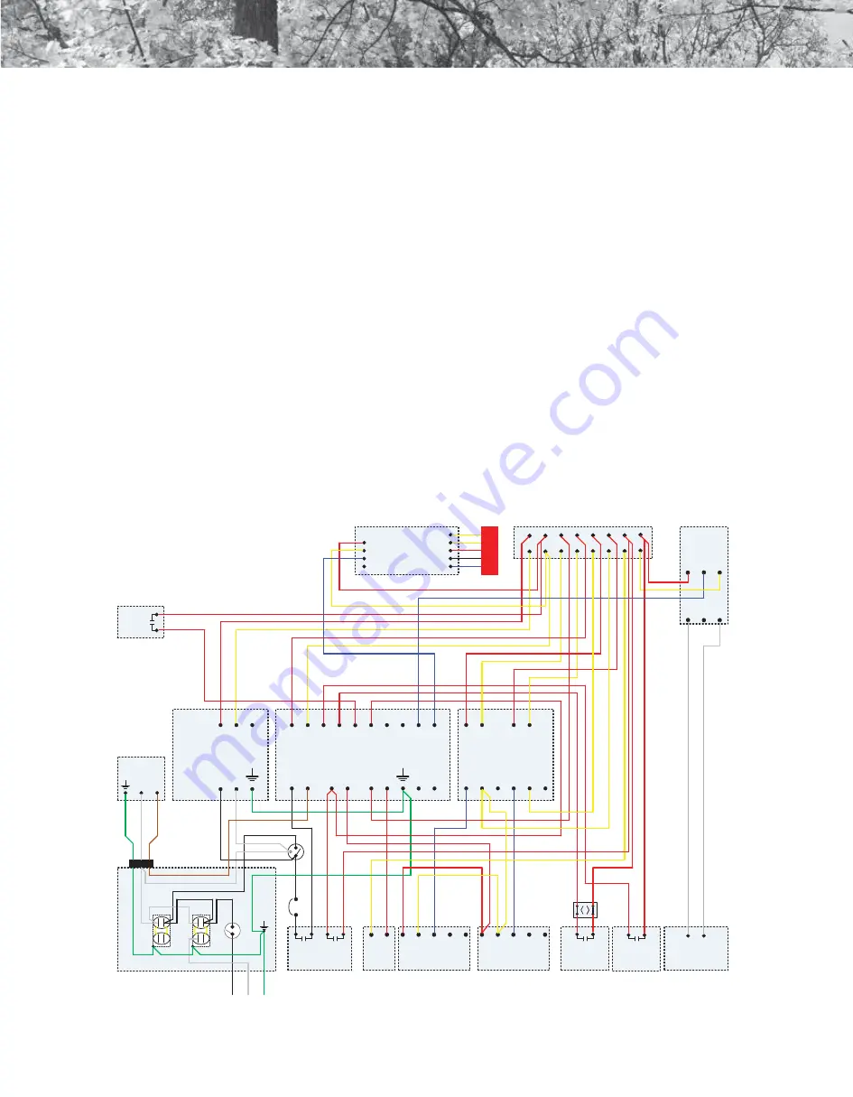
ELECTRICAL SCHEMATIC
position targeted by the control inspect the plate for
creosote, ice, or other build-up. Loosen and clean the
plates if necessary.
»
To remove the damper plates remove the two actuator
mounting bolts. Remove the actuator and the damper
plate should slide off the shaft. If the plate is stuck, pry it
off and clean as necessary.
»
The damper plates may be lubricated with a light
coating of automatic transmission fluid if necessary.
»
If the damper plate is not stuck but the actuator will not
turn test the electrical at the actuator.
»
The “mode” selector should be set to mode 3.
»
Remove the screw in the electrical cover of the
actuator. Pull and wiggle gently on the cover to remove it
from the actuator. Take care not to damage the electrical
pins in the plug.
To test for proper operation the furnace should be powered
on and calling for heat. The display should indicate the
target Top and Bottom Air %. In this state, you may test for
power across terminals 1 & 2 on the actuator. There should
be 24V DC across those terminals.
•
If there is no power across terminals 1 & 2 then confirm
there is power at the Siemens control. If there is no power
at the control check the power supply (see Power Supply
Section). The control signal to the actuator can be tested
from terminal 2 to 3. There should be 2-10V DC. The
actuator position can be confirmed by testing the DC
voltage across terminals 2 and 5 on the actuator. It should
be 2 to10V DC depending on the position of the actuator.
»
If the damper plate is not stuck and there is power and
communication from the control, the damper actuator is
faulty and should be replaced. Please consult your local
dealer for assistance.

