background image

1.3. Steelwrist Design Philosophy

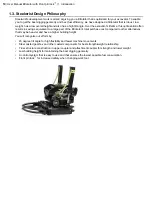
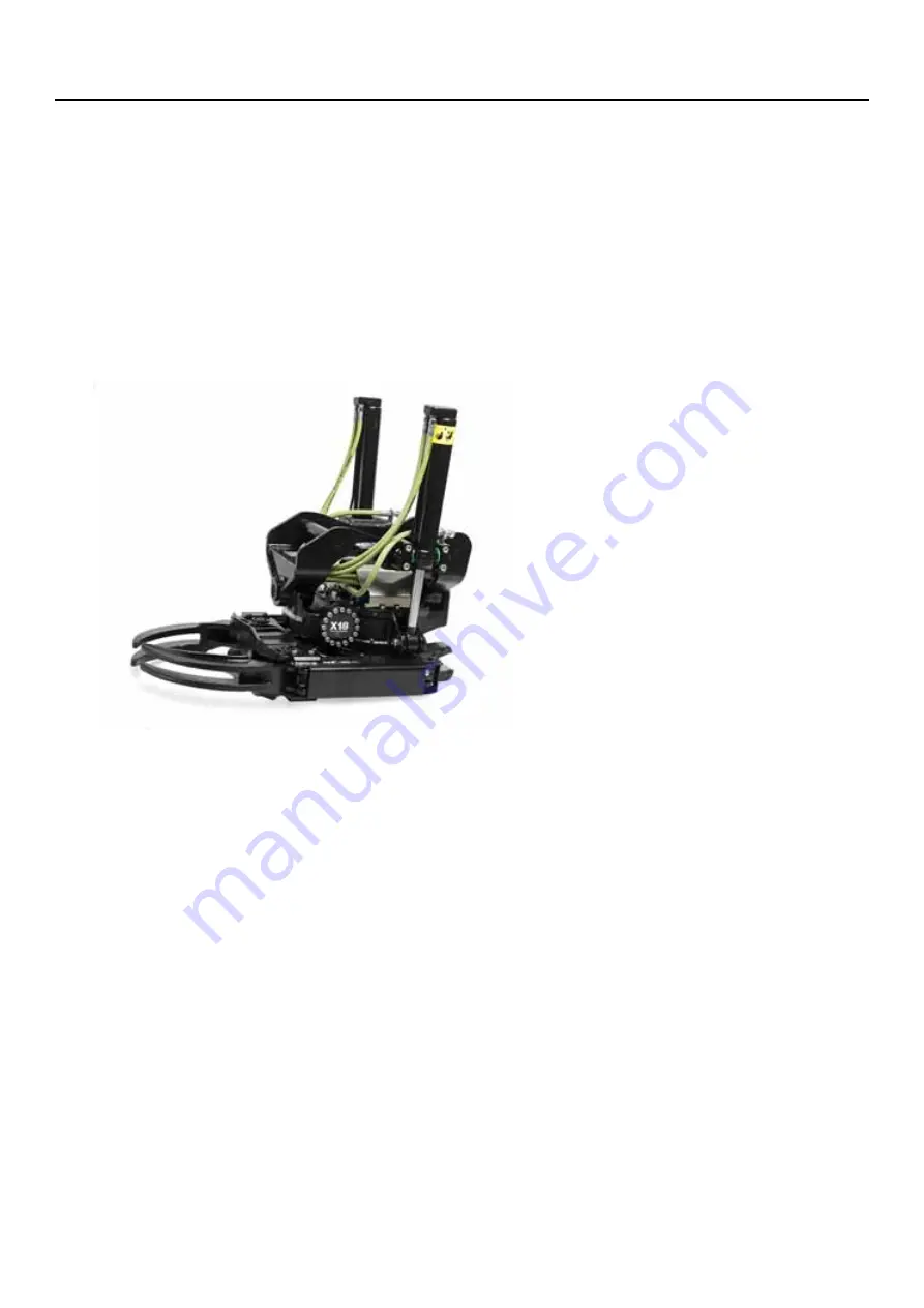
Steelwrist's development work is aimed at giving you a tiltrotator that is optimized for your excavator. To enable
you to get the best digging geometry and best fuel efficiency, we have designed a tiltrotator that is robust, low
weight, has a low overall height and also has a high tilt angle. Over the excavator's lifetime, this optimization often
results in savings equivalent to a large part of the tiltrotator's total purchase cost compared to other alternatives
that may be heavier and have a higher building height.

You will recognize our efforts by:

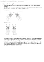
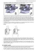
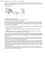
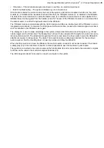
45 degree tilt angle for high flexibility and fewer machine movements

Steel casted gearbox and other casted components for best strength/weight relationship

Truss structure construction in upper coupler and attachment coupler for strength and lower weight

Low building height for maintaining the best digging geometry

A control system that is easy to use and that ensures the lowest possible fuel consumption.

Front pin lock

for increased safety when changing work tool.

10

| User Manual tiltrotator with Front pin lock

| 1. Introduction

Summary of Contents for Tiltrotator Front pin lock X04

Page 1: ...User Manual Tiltrotator Front pin lock X04 X06 X07 X12 X18 X20 X26 XControl G2 DocNo 700347ENA ...

Page 2: ......

Page 3: ...User Manual Tiltrotator Front pin lock X04 X06 X07 X12 X18 X20 X26 XControl G2 DocNo 700347ENA ...

Page 4: ...26 Published by Steelwrist AB Bäckvägen 18 192 54 Sollentuna Sweden 46 626 07 00 www steelwrist com Translation of Original User Manual Copyright 2013 Steelwrist AB No part of this document can be reproduced 4 User Manual tiltrotator with Front pin lock Introduction ...

Page 5: ...echnical data hydraulics 28 4 3 Technical data weights and dimensions 29 4 4 Technical data gripper cassette 29 4 5 Tightening torque 29 5 Operation 31 5 1 Operating the lock function 32 5 2 Operation of the tilt function 32 5 3 Operating of the rotation function 33 5 4 Operation of the extra function 33 5 5 Operation of the gripper function 33 5 6 Other functions 34 5 7 Operation of the excavator...

Page 6: ... interface Wheels Track steering 52 8 Environmental aspects 55 8 1 Environmental information 56 9 Maintenance 57 9 1 General Maintenance 58 9 2 Grease and hydraulic oil 58 9 3 Axial and radial play 58 9 4 Checkpoints 59 9 5 Lubrication points 60 9 6 Full Service 60 9 7 Check list Delivery of the machine 61 9 8 Check list Weekly inspection and lubrication 61 9 9 Check list Daily inspection and lubr...

Page 7: ...Chapter 1 1 Introduction Topics EC Declaration of Conformity Thank you for choosing a tiltrotator from Steelwrist Steelwrist Design Philosophy ...

Page 8: ...y Date The above machine meets the requirements of the Directive 2006 42 EC and the following parts of harmonized standards and technical specifications as stated below SS EN474 1 2006 A1 2009 SS EN474 5 2006 A1 2009 SS EN12100 2010 ISO DIS13031 2 This declaration and Steelwrist guarantee is void if changes or other interventions are made without Steelwrist approval The technical documentation for...

Page 9: ... inadequate inspection and maintenance or incorrect operation Steelwrist products are CE marked This means that they are designed manufactured and described in accordance with current directives and requirements However it is important that all security requirements are considered in the installation maintenance and use This is the case for safety regulations in this manual the excavator s manual ...

Page 10: ...se cost compared to other alternatives that may be heavier and have a higher building height You will recognize our efforts by 45 degree tilt angle for high flexibility and fewer machine movements Steel casted gearbox and other casted components for best strength weight relationship Truss structure construction in upper coupler and attachment coupler for strength and lower weight Low building heig...

Page 11: ...Chapter 2 2 Safety Topics Safety Levels Safety regulations Machine plate and warning labels Type certificate for lifting hook ...

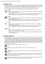
Page 12: ...our attention to that can increase or reduce the performance of the product or of your excavator Carefully read the user manual for your excavator together with this manual to ensure best possible function and performance 2 2 Safety regulations Steelwrist tiltrotators can be used with a variety of tools that correctly used increase the excavator s productivity significantly Work tools however have...

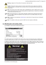
Page 13: ... breakers Note Follow the recommendations in Maintenance to reduce the risk of injury and ensure the longevity of the tiltrotator Note The indication on the quick coupler can differ from other couplers and tiltrotators 2 3 Machine plate and warning labels Your tiltrotator is marked with a machine plate as follows The machine plate shows the tiltrotator model serial number maximum lift weight with ...

Page 14: ...a around tiltrotator is three meters Be extra cautious when handling long objects Always check that any attachment is properly locked after each change Do not exceed the machines lifting capacity Never use the tiltrotator to lift persons Never leave the operators cabin with the tiltrotator lifted For questions contact your dealer or Steelwrist 14 User Manual tiltrotator with Front pin lock 2 Safet...

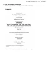
Page 15: ...2 4 Type certificate for lifting hook The following type certificate is valid for lifting hooks used on Steelwrist products User Manual tiltrotator with Front pin lock 2 Safety 15 ...

Page 16: ......

Page 17: ...Chapter 3 3 Product Description Topics Function description Tilt rotator main parts Hydraulic system Electrical control system ...

Page 18: ...can be divided into dedicated mounting standards quick coupler that fit on one bucket type that must comply with the standard and universal standards quick coupler that fit with different types of buckets mainly various original buckets from different manufacturers of excavators Various attachment standards have different performance in terms of height weight width and surface structures for assim...

Page 19: ...ive wear and tear the driver should always endeavor to balance the digging force along the work cutting edge Also consider the following The tiltrotator is not intended for continuous rotation for a long time grilling type of work Reason being risk of overheating and pinching Do not expose the tiltrotator to abnormal forces for example by hitting buckets to hard surfaces Avoid exposing the tilt cy...

Page 20: ...e with a hydraulic cylinder the locking cylinder and locking pins For a secure locking function it is essential that the locking pins enclose the pins of the work tool When the locking cylinder is in its retracted position the lock is open and it is possible to connect or disconnect a work tool Front pin lock is a safety function that locks the front bracket pin of the work tool in the attachment ...

Page 21: ...uch as a gripper cassette or other hydraulic tool Gripper The gripper unit facilitates the handling of goods within the frame for permitted lifting capacity The gripper unit in principle consists of two hydraulic cylinders gripper cylinders and two gripper arms In order to maintain the hydraulic pressure without continuous active flow the respective gripper cylinder is equipped with a pilot contro...

Page 22: ...trotator is equipped with proportionally controlled directional valves which together with carrier machine valves are controlled from a control unit to steplessly regulate the oil flow speed and its direction XControl This type of system is flow compensated when running multiple functions simultaneously A simpler version is also available where the direction of flow is regulated by On Off valves a...

Page 23: ...surized The locking pins are retracted and the lock opens Note for certain types of attachments such as Verachtert standard the inverse relationship is valid i e the lock is closed when the locking pins are retracted If the gripper cassette is mounted the gripper function will be activated by activation of the directional valve for gripping function In order to maintain the hydraulic pressure the ...

Page 24: ...ltrotator XCG2 RF 3m 16 1 Cable XCG2 TR 17 802219 1 Cable XCG2 Generic Power Adapter 18 801069 1 QC Enable Plug XCG2 19 7 8 8 9 13 14 15 16 12 11 5 3 17 10 2 8 On Tiltrotator 18 Safety gate Machine QC Lockout Machine Power 20 20 6 1 Tiltrotator module 2 Cabin module 3 Display 4 Handle Left 5 Handle Right 6 Attachment coupler switch QC switch 7 Feeder valve 8 Handle Display wiring Can Cable 9 T ada...

Page 25: ...or which is installed in the tiltrotator s worm gear The display 3 is used to make all settings in the system and provide information about the system e g tilt and rotation angle via the Clinometer The display does not need to be connected for the system to work and can be disconnected via switch The attachment coupler switch 6 is used when the driver wants to open the tiltrotator s attachment cou...

Page 26: ......

Page 27: ...Chapter 4 4 Technical data Topics Technical data Technical data hydraulics Technical data weights and dimensions Technical data gripper cassette Tightening torque ...

Page 28: ...gle 1250 900 800 400 500 300 250 150 Rec Bucketvol lit Max 1800 Max 1800 Max 1600 Max 1400 Max 1300 Max 1200 Max 1100 Bucket width mm DF Direct fitted 4 2 Technical data hydraulics Table 3 Technical data Hydraulics X26 X20 X18 X12 X07 X06 X04 80 120 80 120 60 100 50 70 30 50 30 50 30 40 Required flow L min 180 210 180 210 180 210 180 210 180 210 180 210 180 210 Working pressure bar 210 210 210 210...

Page 29: ...e lifting capacity is reduced by 50 The gripper arms must not be subjected to greater force than the maximum lifting capacity Table 5 Lift Weights X26 X20 X18 X12 X07 X06 X04 1200 900 900 500 500 350 350 Max Lift Weight kg 4 5 Tightening torque The table below gives the recommended tightening torques for different mounting screws Certain screw dimensions can be found in different versions and can ...

Page 30: ...0 X18 X12 X07 X06 X04 M20 12 9 649Nm M20 12 9 649Nm M20 12 9 649Nm M20 12 9 649Nm M16 12 9 333Nm M20 12 9 649Nm M20 12 9 649Nm Gripper cassette 30 User Manual tiltrotator with Front pin lock 4 Technical data ...

Page 31: ...Operation of the tilt function Operating of the rotation function Operation of the extra function Operation of the gripper function Other functions Operation of the excavators quick coupler Connecting work tools Disconnecting work tools Using the lifting hook ...

Page 32: ...s that the lock is no longer in a secured position A warning symbol appears on the display if a display is installed 2 Build up hydraulic pressure by operating any of the features in the tiltrotator via the joystick The tiltrotators attachment coupler is opened 3 When the safety switch is pushed back to locked the locking valve will lose power and the locking cylinder will start to close 4 Ensure ...

Page 33: ...from above 5 4 Operation of the extra function Caution The description below refers to standard settings and can sometimes vary depending on the driver settings and joystick selection The tiltrotators extra function if such is mounted is controlled by activating the right index finger roller on the joystick The higher the activation of the roller the larger the flow to the auxiliary function Maxim...

Page 34: ...ation See the documentation from your supplier installer Warning See the quick coupler and the carrier machine s user manual for further information regarding its operation The process for making it possible to control the excavators quick coupler is the following 1 Set tiltrotator on a flat surface 2 Exit the machine and disconnect the tiltrotator cable and hydraulic lines from the connectors on ...

Page 35: ...ket pin make sure no hydraulic hoses are damaged on the work tool if such hoses exists 2 Crowd in the tiltrotator so that the work tool hangs in the work tools front bracket pin 3 Activate the quick coupler safety switch The locking pins will be retracted and the work tools rear bracket pin enters its position See Operation of the tiltrotator locking function User Manual tiltrotator with Front pin...

Page 36: ...l in an extended position and push the front end of the work tool to the ground Pull in the dipper arm cylinder with the work tool pressed to the ground in order to ensure that the locking pins lock the rear bracket pin under load b Lift the work tool and shake c Is it not to possible to determine if the coupler is locked exit the machine and check that the coupler is properly locked 5 9 Disconnec...

Page 37: ...pler is released from work tools front bracket pin 5 Turn the quick coupler safety switch off pressurize the system and the locking wedge will be pushed out to the locked position This is indicated by a green indicator bar right becoming visible and the red indicator bar left no longer being visible 5 10 Using the lifting hook The lifting hook must always be used with great care Always check lifti...

Page 38: ...ct and that protective lugs are in place 2 Place the shackle strap on the lifting hook so that the lift takes place within the marked area 3 Ensure that the safety area is free of anyone who could be hurt or anything that could be damaged if the object being lifted should fall 38 User Manual tiltrotator with Front pin lock 5 Operation ...

Page 39: ...Chapter 6 6 User interface Topics Understanding the user interface Operating mode Menu Speed Brightness Profile Management Layout Clinometer Troubleshooting Troubleshooting in out signals Language ...

Page 40: ...of buttons where you choose between different options and other information that you may find useful Some more advanced setting features are hidden as these are intended for service personnel If you get support by phone you can sometimes be asked to go into service mode In that case you will get the guidance you need to get there In the navigation bar all available buttons are indicated as colored...

Page 41: ...ol the menu button By pressing the Menu button you will come to various system settings 6 Help Button for help texts and explanations for the current menu 6 3 Menu In the menu you can change settings or access the various information systems The menu is divided into two different screens as follows The following choices can be made Speed Adjust speeds for different functions Brightness Adjust the ...

Page 42: ...nu If you do not want to save settings press Cancel on the left side of the navigation bar 6 5 Brightness In the Brightness menu you can adjust the day night mode brightness and time to screen save mode 1 In the top part of the working area there are two buttons one for day mode sun and one for night mode moon Choose a screen mode that you feel comfortable with 2 Adjust the brightness by dragging ...

Page 43: ... by green edges 3 Select the profile you want to rename 4 Enter the new name using the touch screen keyboard 5 Press the OK button on the right of the navigation bar to save the settings and the system goes back to the Main menu If you do not want to save settings press Cancel on the left side of the navigation bar To copy a profile to another select Copy Profile as below 1 Use the drop down menu ...

Page 44: ...utton 7 and activating S1 roller Change the layout for left and right handles by pressing the arrow buttons in the navigation bar To return to a higher level press Cancel on the left side of the navigation bar 6 8 Clinometer The clinometer is a useful tool that indicates how your work tools are oriented The clinometer shows the tilt angle the bucket and rotation angle of your work tool The tilt an...

Page 45: ...y the outputs signals Active errors are analyzed as follows 1 Use the drop down menu to select the Active Errors 2 If the system detects an error each error will be displayed with an error code Each error code generates a button on the touch screen 3 Press the error code for the error and explanation of the error code appears as follows Example Historical errors are reviewed as follows To delete h...

Page 46: ...aged Outputs are tested as follows Keys and rollers generate input signals that the control system then converts to output signals for the various functions Green symbol indicates that the outgoing signal is ok For analog signals ie rollers you can also see the value generated by the system in mA When the output signal has two directions shown by right and left arrow indicated as shown above Yello...

Page 47: ...of the navigation bar to save the settings and the system goes back to the Main menu If you do not want to save settings press Cancel on the left side of the navigation bar User Manual tiltrotator with Front pin lock 6 User interface 47 ...

Page 48: ......

Page 49: ...Chapter 7 7 Wheels and Track steering Option Topics Introduction Wheels Track steering Function description Wheels Track steering User interface Wheels Track steering ...

Page 50: ...It must be connected so that it is not possible to drive faster than 20 km h with handle steering activated If handle steering indicates a problem the system must switch to safe mode i e switch off The regulatory framework for track steering is not as stringent but some of the points above also apply here Above all that handle steering must be activated manually indicated visually and be possible ...

Page 51: ...dle steering without also installing tiltrotator steering The wheels track steering module communicates with other modules via CAN bus An activation on a roller in the handle 1 is sent via the cabin module on to the wheels track steering module 4 The signals are translated here and current sent to solenoid valves on the Wheels steering block Track steering block 5 Activation and shut off of the wh...

Page 52: ...h Flashing red light off and reactivation will be required The roller in the handle must in any case reach the neutral position before the steering function can be restored Note If the steering wheel is activated at the same time as operating handle steering the steering wheel has priority and the roller on the handle must be released back to the neutral position before handle steering can be used...

Page 53: ...g left or right Track control Individual means that you can run the left track forwards or backwards with the left index finger roller and run the right track forwards or backwards with the right index finger roller Consult the machine s documentation for more detailed information on how to install it on your excavator User Manual tiltrotator with Front pin lock 7 Wheels and Track steering Option ...

Page 54: ......

Page 55: ...Chapter 8 8 Environmental aspects Topics Environmental information ...

Page 56: ...ng apply for recycling and waste management Steelwrist products are manufactured with the purpose that as much as possible should be recycled The majority of components are made from recyclable materials Metals is the material that is easiest to recycle Generally we recommend that recyclable materials are handled through an approved recycling company Metals are the largest part of the weight of St...

Page 57: ...al Maintenance Grease and hydraulic oil Axial and radial play Checkpoints Lubrication points Full Service Check list Delivery of the machine Check list Weekly inspection and lubrication Check list Daily inspection and lubrication Feedback ...

Page 58: ...Hydraulic oils must be approved for use with O rings of material NBR70 9 3 Axial and radial play The tiltrotator is designed so that a minimal play is possible in both axial and radial direction This is necessary because the friction between sliding surfaces generates heat and as this affects the various metals differently The tiltrotator otherwise risk to pinch After a certain time in operation t...

Page 59: ...es manifolds connectors and hydraulic hoses Verify that cable connections to all the valves are intact and that there are no hydraulic leaks on around the manifold 6 Tilt cylinder holder and bushings Check that the tilt cylinder holders are tightly secured and the mounting is undamaged 7 Lock cylinder with locking bolts and play in locking pins 8 The lock indications are intact 9 Visually check th...

Page 60: ...4 Gripper shaft 9 6 Full Service Over time it may be advantageous to replace wear parts such as slide bushings slide bearings shaft bushings hydraulic hoses etc Steelwrist has a full service program for this where your tiltrotator is inspected and all wear parts are replaced for a fixed price Steelwrist recommendation is to conduct a review of the tiltrotator approximately every second year Contac...

Page 61: ...ng screws for tilt cylinder brackets worm flange top cover and gripper cassette are intact and tight 9 Make sure the cable harness is intact and undamaged 10 Check radial and axial play 11 Check all shaft bearings for wear and tear Excessive wear can cause costly consequential damages 12 Check that warning labels are present and readable 13 Lubricate the tilt cylinder brackets grease nipples 2 4 p...

Page 62: ...___________________________________________ ___________________________________________________________________________________________________ ___________________________________________________________________________________________________ ___________________________________________________________________________________________________ ________________________________________________________...

Page 63: ......

Page 64: ...Steelwrist AB Bäckvägen 18 192 54 Sollentuna Sweden 46 626 07 00 www steelwrist com 700347ENA ...

Reviews: