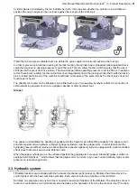
(or B) port in order to run the function in a certain direction. The oil is routed back to through the B (or A) port to
the tank line (T). Up to five functions are controlled by the hydraulic system, rotation, tilt, grab (EXTRA1), EXTRA2
and attachment coupler lock.
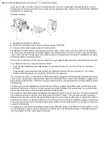
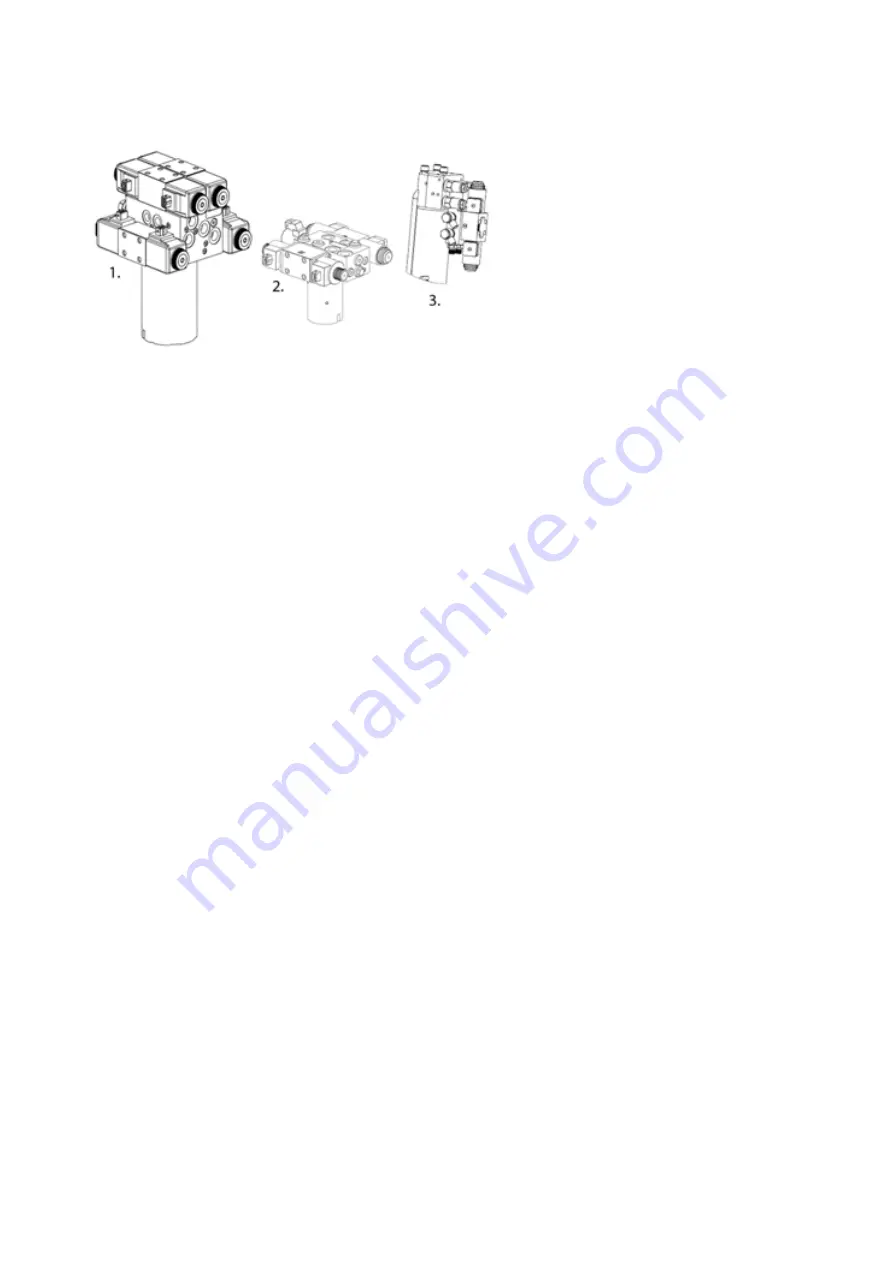
Tiltrotator manifold:
1.
Manifold with all valves in tiltrotator
2.
Divided manifold with rotation, lock and extra functions in tiltrotator
3.
Tilt valve with counter balance valves in the tilt cylinder.
The tiltrotator manifold includes main pressure reduction valve, check valves and shock valves for tilt cylinders.
The chock valve will protect the tilt cylinders against overload and open at 210 bar. The main pressure reduction
valve is set to 210 bar. The hydraulic oil is routed trough a six channel swivel connected in manifold on its way to
the locking cylinder and extra functions.
There is also a relief valve on the engine to protect the engine against peak pressure (not applicable to X04-X07).
In principle there are three types of control as follows:
•
Proportionally controlled system that requires one hydraulic function (i.e. two hoses) from the excavator -
XControl.
•
Proportionally controlled system that requires two hydraulic functions from the excavator (i.e. four hoses).
•
On/Off system that requires one hydraulic function from the excavator.
The current most common configuration is that the tiltrotator is equipped with proportionally controlled directional
valves, which, together with carrier machine valves, are controlled from a control unit to steplessly regulate the oil
flow (speed) and its direction - XControl. This type of system is flow compensated when running multiple functions
simultaneously.
A simpler version is also available where the direction of flow is regulated by On/Off valves, and the flow via the
excavator's foot pedal. In this type of control system the hydraulic oil takes the "easiest way", ie the function that
has the lowest load when running multiple functions simultaneously.
There is also a variant that requires two double-acting hydraulic functions from the machine. The valves in tiltrotator
then decide where only the features that will be active through 4:2 valves. The excavators machine hydraulics
determines the direction and flow of hydraulic flow through 4:2 valves that are either open or closed. The rotation
is directly connected to a separate hydraulic circuit and other functions (tilt, lock, additional, gripper) is connected
to the second hydraulic circuit. This means that only the rotation and one other function (ie, tilt, grab, or extra) can
be used simultaneously.
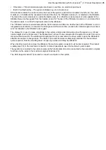
It is important to understand the principles and hence the difference between the different control systems in order
to set the tiltrotator properly and thus get maximum performance. The table below shows a schematic diagram of
how the hydraulic and the control systems interacts.
22
| User Manual tiltrotator with Front pin lock
™
| 3. Product Description
Summary of Contents for Tiltrotator Front pin lock X04
Page 2: ......
Page 16: ......
Page 26: ......
Page 48: ......
Page 54: ......
Page 55: ...Chapter 8 8 Environmental aspects Topics Environmental information ...
Page 63: ......
Page 64: ...Steelwrist AB Bäckvägen 18 192 54 Sollentuna Sweden 46 626 07 00 www steelwrist com 700347ENA ...

