


V06-2017
ST2520
8
7.0 OPERATION OVERVIEW.
The three switches on the ST2520 front switch board have the following symbols:
I = on 0 = off
1.
Main power switch (fig. 1 page 9)
2.
Power On indicator lamp (fig. 1)
3.
Switch illuminated ground glass, see 13 (fig. 1)
4.
Switch for working lamp with dimmer (fig. 1)
5.
Speed control by hand with centre click (fig. 1)
6.
Knob for dimmer working lamp (fig. 2 page 9)
7.
Alignment of time from 0 (standstill) to maximum
wind speed for foot switch / control (fig. 3 page 9)
Use slotted screwdriver 2,5x0,6mm
8.
Alignment of time from 0 (standstill) to maximum
wind speed for speed control by hand (5) (fig. 3)
Use slotted screwdriver 2,5x0,6mm
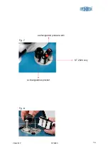
9.
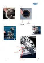
Guide rollers, switchable for 16 / 17,5 / 35mm (fig. 9 page 17)
10.
Counter pick up with interchangeable sprocket for 16mm and 35mm
(fig. 7 – 8 page 16)
11.
Pressure arm, interchangeable for 16mm and 35mm (fig. 7 – 8 page 16)
12.
16 / 35mm format counter switch (fig. 7 page 16)
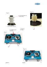
13.
Illuminated ground glass (fig. 11 page 17).
14.
Platform for interchangeable sprockets, guide rollers and
pressure arm (fig. 11)
15. Counter display (optional) (fig. 11)
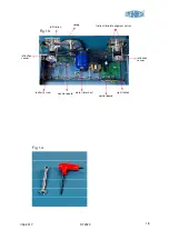
16. Main power inlet (fig. 5 page 10)
17. Main power fuses (fig. 5)
18. Fuse for ground glass (fig. 5)
19. Working lamp socket (fig. 5)
20. Foot switch / control (reverse / left - fig. 6 b page 10)
Foot switch / control (forward / right - fig. 6 b)
22. Film ruler for 16mm and 35mm (fig. 11 page 17)
23. Time elapsed counter (fig. 4 page 10)
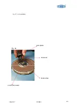
24. Special roller (toothless) for counter (fig.10 page 17) optional
( for damaged / shrunken film)
Front castor with brake (fig. 6
)


