10
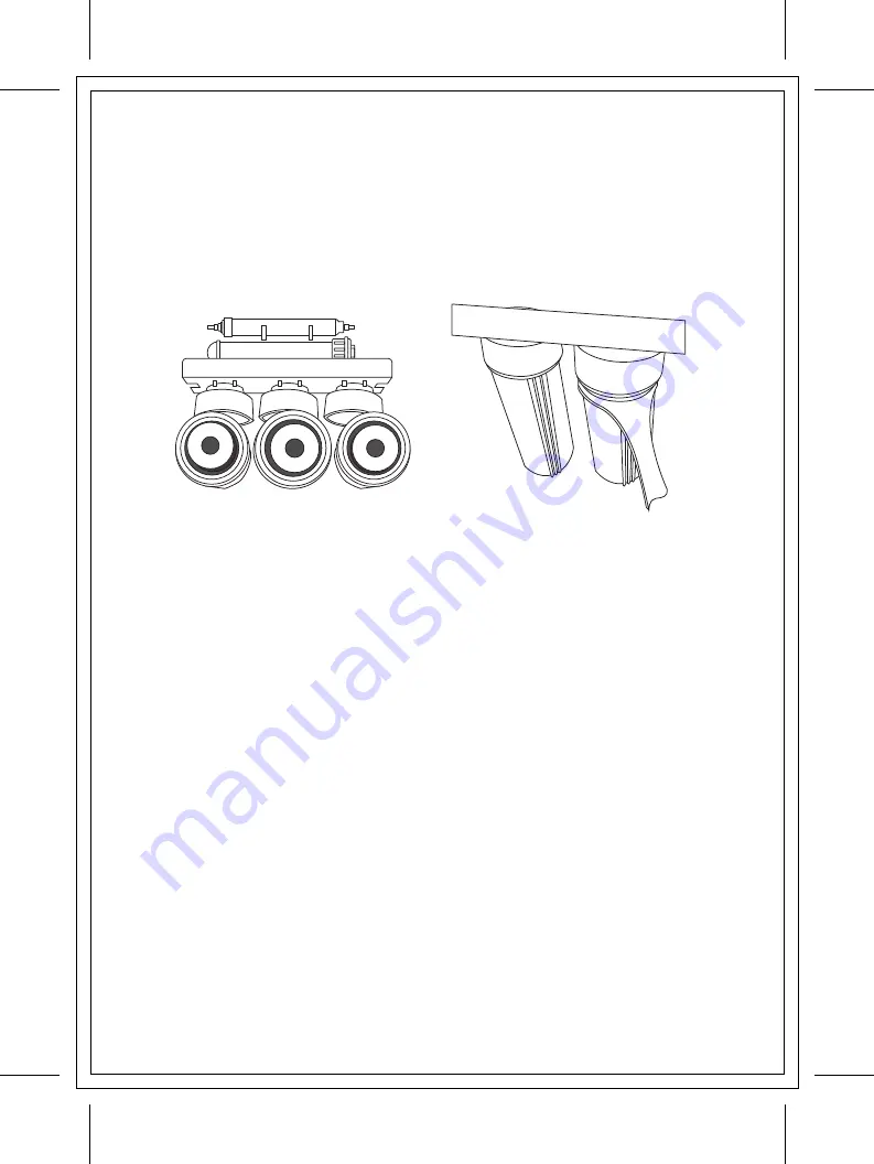
1. Remove
fi
lters from packaging and insert into
fi
lter housings
2. Connect the 3
fi
lter housing head sections to each other using the connec
tors provided
3. Connect the joined
fi
lter housing head units to the manifold bracket using
the screws provided
4. Connect the Membrane housing with membrane already inserted to the top
of the manifold bracket
5. Connect the in line carbon
fi
lter to the membrane using the clips provided
6. Screw on each of the
fi
lter housings to the
fi
lter head units using the
wrench
provided, be careful to ensure they are placed in the correct position as
marked on the manifold bracket
STEP 5 – STORAGE TANK PRE FILL & LOCATION
1. Wrap the Te
fl
on tape around the thread on the top of the storage tank
2. Connect the ball valve to the top of the tank, tighten
fi
rmly without over
tightening
3. Connect desired length of tubing to the ball valve and directly to the ball
valve at the main water connection
4. Open both ball valves and pre
fi
ll the storage tank.
5. Once
fi
lled, turn o
ff
both ball valves and remove tubing from the main water
connection ball valve
6. Position storage tank in the desired position sitting it on the plastic stand
provided as close to 5
fi
lter components and manifold
1
2
3
4
5
6
STEP 4 – 5 FILTER COMPONENTS &
MANIFOLD INSTALLATION
Select the location for the Reverse Osmosis components under your sink. Allow
space for the storage tank and at least 50mm to the underside of the housing
to cater for
fi
lter cartridge changeover.
Summary of Contents for Reverse Osmosis
Page 1: ......


