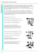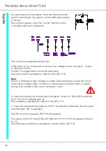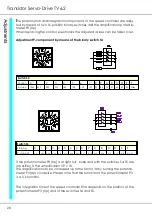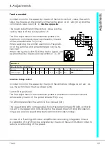
Transistor Servo-Drive TV6.2
32
The commutation limit must be checked when using a dc motor
with a permanent excitation (no field) and iron core. The motor
data sheets show the limiting curve of the permissible motor current
dependent on the speed. The maximum torque of the motors,
which corresponds to the maximum current, is 3 to 6 times the value
of the continuous torque. For servo-amplifiers it is twice the value.
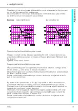
Take this motor curve as an example. The linear
limit characteristic of the servo-amplifier must be
within the motor characteristic.
The limiting line for the amplifier is drawn at 2 x
I-rated (which corresponds to 10V current com-
mand value). Then the straight reduction line is
drawn tangentially to the motor characteristic.
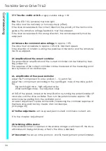
1.
Determine the max. permissible current for
maximum speed (triggering point IN2 [%])
2
.
Determine the slope s of the current straight
reduction line up to maximum speed.
3
.
4.
5
.
Determine the first break point with Zener voltage
Uz [V]
6.
Determine the starting point of the current re-
duction with IN1 [%]
7.
On delivery the devices are equipped with the
following components: R190, R111, R112, and
DZ2. The values are indicated in the following ex-
ample:
Summary of Contents for TV 6.2
Page 12: ...Transistor Servo Drive TV 6 2 12 ...
Page 13: ...TV6 2 13 3 Mechanical Installation ...
Page 14: ...Transistor Servo Drive TV 6 2 14 ...
Page 15: ...TV6 2 15 3 Mechanical Installation ...
Page 17: ...TV6 2 17 4 Adjustments Anschluss Kompaktgerät Anschluss Mehrachskombination ...
Page 38: ...Transistor Servo Drive TV6 2 38 ...
Page 39: ...TV6 2 39 8 Circuit Diagrams ...
Page 40: ...Transistor Servo Drive TV6 2 40 ...
Page 41: ...TV6 2 41 8 Circuit Diagrams ...


