background image


STEIN300_Hubzentriereinrichtung_HZEV_03_GB.DOC_D / 02.2020  

2


Introduction 

The safety of all persons who come into contact with the HZEV depends fundamentally 

on knowing how the HZEV functions. Therefore: 

Read these operating instructions before using the equipment for the first time. 

These operating instructions contain important information which will ensure the correct, 

economical and safe operation of your HZEV. 

2.1


Short description 

Lift centring devices are installed in the STEIN 300 Workpiece Transport System. 
In conjunction with the workpiece carrier transport system, the HZEV enables the follo-

wing: 


exact positioning of workpiece carriers (and therefore of the workpieces located on 

them), 


a further lift of the WT in the Z axis 


workpiece carrier elevation and support while power transfer operations are carried 

out on workpieces. 


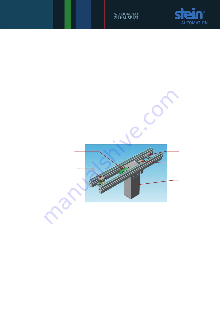
Fig. 2-1: 

Lift centring device 

- Components 


Other advantages of these devices are that 


the belt element is not under tension while the workpiece is being processed and  


belt wear is reduced. 


Please note: 

From a stroke of 250mm, the WT must additionally be centred from above in the end 

position by means of suitable centring pins, as otherwise the specified centring 

accuracy is not given. These centring pins are not included in the scope of delivery. 


Pre-stopper 

Reading head 

(optional) 

Stopping de-

vice 

HZEV 

Surface 

switch 

Summary of Contents for 300

Page 1: ...C 02 2020 1 Lift centring device with extended stroke HZEV STEIN Workpiece Transport System STEIN 300 Operating instructions Attention all installation operating and maintenance personnel always keep these instructions by the lift centring device ...

Page 2: ...cumentation may not be altered distributed reproduced or transferred to third parties without the prior written permission of STEIN Automation STEIN Automation GmbH Co KG Carl Haag Straße 26 78054 VS Schwenningen Germany Telephone 49 0 7720 8307 0 Publication date February 2020 We reserve the right to make changes to the design and construction ...

Page 3: ... repair work 10 4 Technical description 11 4 1 Scope of delivery 11 4 2 Installation area 11 4 3 System components 12 5 Installing the lift centring device HZEV 13 5 1 Procedure 13 5 2 Preparation 14 5 3 Installing the HZEV between the two belt profiles 14 5 4 Fitting the stopping devices 16 5 5 Compressed air and power connections 16 5 6 Installing safety equipment 17 6 Initial operation 18 7 Ope...

Page 4: ...rnings are de scribed in detail in chapter 3 1 1 Explanation of safety and warning notices The following safety notices indicate all actions where there is danger to life and limb for system operators or their colleagues Strictly comply with these instructions and act with particular care in these cases Pass the safety notices on to all other users DANGER The sign indicating DANGER means immediate...

Page 5: ...ical voltage It appears for all working and operating procedures that must be followed precisely in order to avoid injury to personnel or damage to the system through high voltage Other warning signs ATTENTION This sign stands for instructions which if not followed could endanger the system Protective clothing must be worn Wear your personal safety clothing Safety footwear hard hat goggles and saf...

Page 6: ... the HZEV enables the follo wing exact positioning of workpiece carriers and therefore of the workpieces located on them a further lift of the WT in the Z axis workpiece carrier elevation and support while power transfer operations are carried out on workpieces Fig 2 1 Lift centring device Components Other advantages of these devices are that the belt element is not under tension while the workpie...

Page 7: ...r damages caused in transit to be accepted follow this procedure Inform the freight company Draw up a damage report giving the following details Name and address of recipient Item or order number A description of the damage Send components if possible in their original packaging with the damage report back to the manufacturer 2 4 Warranty For the lift centring devices with extended stroke as well ...

Page 8: ...on installation staff users and service technicians must ob serve the notices and warnings contained in these operating instructions Lift centring devices with extended stroke must only be installed and repaired by au thorised personnel who have been trained by STEIN Automation Only genuine components from STEIN Automation may be used when carrying out repairs on the open lift centring devices 3 2...

Page 9: ...ift centring device invalidate the warranty STEIN Automation accepts no liability for any damage caused by unauthorised interventions modifications or repairs 3 3 Residual danger The lift centring device with extended stroke is manufactured using state of the art tech nology and to recognised safety standards Nevertheless their use can lead to dangerous situations for users or third parties or to ...

Page 10: ...warning signs to prevent the system from being started up while installation and repair work is being done 4 Remove all workpiece carriers from the affected belt element 5 Carry out the work in accordance with the descriptions in this documentation complying with relevant safety and accident prevention regulations and in a technically correct manner and with the greatest possible accuracy 6 After ...

Page 11: ...uate length at least 850 mm i The following accessories do not form part of the scope of delivery Full enclosure supplied and installed by the customer Full enclosure Cylinder STEIN Automation option Control system STEIN Automation option Stopping device STEIN Automation option 4 2 Installation area Installing an HZEV will be required in automatic workplaces if workpiece carriers have to be very a...

Page 12: ... by the two transport belts until they reach the work station stopping device STEIN Automation option The position query triggers the mo vement of the lifting unit and raises the workpiece carrier After processing in this raised position the elevating platform is lowered and the workpiece carrier is transferred onto the belt elements transport belts Elevating platform Workpiece carrier ...

Page 13: ...e installation procedure is divided into 6 phases Preparation Installing the HZEV between the edges of the two belt profiles Fitting the stopping devices Assembling the pneumatic components Connecting up the power and compressed air supply and Fitting the safety equipment ATTENTION On operating stations which generate shavings for example drilling or thread cutting machinery covers should be insta...

Page 14: ...rt system from its compressed air supply 3 Put up warning signs to prevent the system from being started up while installation and repair work is being done 4 Remove any workpiece carriers located on the affected belt element 5 3 Installing the HZEV between the two belt profiles Protective clothing must be worn Wear your personal safety clothing Safety footwear and safety gloves ATTENTION If large...

Page 15: ...m below The HZEV has been inserted 3 Straighten the HZEV 4 Turn the screws with sliding blocks 90 again so that the HZEV hangs in the profile tighten the screws Fig 5 4 Installation measurements Adjustment range for cylinder strokes 15 mm Available cylinder strokes 100 125 160 200 250 350 PB Pallet width UB Transfer width A Cylinder stroke 13 B Cylinder stroke 260 C Cylinder stroke 224 D Pallet wi...

Page 16: ...ng pressure 4 bar i Festo GRLA 1 8 QS6 throttle check valves are used as connectors Type PUN S hoses with an exterior diameter of 6mm and wall thickness of 1 mm are used manufactured by Festo Fig 5 5 Connecting the HZEV to the compressed air supply Compressed air connec tions Wiring diagram Connect the HZEV to the compressed air supply using the two screw connections i Connection at top 4 Cylinder...

Page 17: ... purpose machine manufacturer to operate the HZEV only as part of a fully enclosed system Doors and openings in this fully enclosed system must be secured against being opened during operation using safety locks or switches The belts feeding and releasing materials must be fitted with safety tunnel covers of an adequate length at least 850 mm Install the full safety enclosure onto the processing s...

Page 18: ...ea Has all safety equipment been installed and is it working correctly Are any hoses or cables in an area where they may get crushed Once you have carried out all these checks you can continue with the initial operation Switch on the Transport System and its associated processing stations and carry out a trial run Check the functions of the individual elements and processing stations as well as th...

Page 19: ...esent no defective component processing can start If a defective component is detected the WT moves on unprocessed WTs are stopped at the processing station by the stopper Further WTs are stopped at the pre stopper The HZEV extends and the following signal is sent to the top level control system Processing on WT can proceed The workpiece is processed Signal to the WTS control system Processing com...

Page 20: ... valve Compressed air supply cut Restore compressed air supply HZEV does not elevate WTS transport system control failure Restore control system Processing station control system failure Inductive proximity switch not connected to power supply Connect inductive proximity switch to power supply Inductive proximity switch faulty Replace inductive proximity switch Poor contact between plug and socket...

Page 21: ...the workpiece transport system from its compressed air supply 3 Put up warning signs to prevent the system from being started up while installation and repair work is being done 4 Remove any workpiece carriers located on the affected belt element Protective clothing must be worn When cleaning wear goggles safety gloves and a dust mask Only use a vacuum cleaner to remove dust shavings and other par...

Page 22: ...ew between the HZEV and the belt element Tightly fastened Tighten loose screws see chapter 5 Inductive proximity switch Tightly fastened Tightly fasten inductive proximity switches Compressed air hoses Stable connections Re tighten loose con nections Tightly fit push connect ors see chapter 5 Entire HZEV Play functional accuracy Re tighten loose screw connections Accurately re position inductive p...

Page 23: ...oke HZEV Fig 10 1 Lift centring device with extended stroke HZEV 300 110 001 The protective housing for the cylinder 930293001 is not included in the scope of delivery of HZEV The protective housing must be fitted if no protective housing for the cylinder is guaranteed by third parties the HZEV is controlled by STEIN Automation ...

Page 24: ...4 Elevating platform 4 300110008 Centring sleeve 1 300110009 Retaining strip right 4 S31324 DIN912_M6x40 4 S31873 DIN7984_M8x25 4 S31325 DIN912_M8x25 4 S30644 DIN912_M8x35 2 S30299 DIN913_M4x6 4 S31269 T slotted nut M6 1 S32063 Shock absorber kit 2 S31342 GRLA 1 8 QS6 2 S31924 Reduction from 1 8 to 1 4 1 S31358 DIN6321_Form B 1 S31359 DIN6321_Form C 2 S32070 Control stop 2 S31532 Safety sign SL50m...

Page 25: ...STEIN300_Hubzentriereinrichtung_HZEV_03_GB DOC 02 2020 25 10 2 930 293 001 Protective housing cylinder for HZEV OPTIONAL Fig 10 2 Protective housing cylinder for HZEV 930 293 001 optional ...

Page 26: ...26 STEIN300_Hubzentriereinrichtung_HZEV_03_GB DOC_D 02 2020 Quantity Order number Description 1 300110005 Cover 1 300110006 Cover 1 300110007 Cover 4 S31396 DIN912_M5x10 4 S31658 DIN912_M5x8 ...

Page 27: ...der and workpiece carrier 12 kg Workpiece carrier positioning accuracy 0 02 mm in its X and Y axes 0 1 mm in its Z axis if load is centred Permissible WT loading in the X axis 0 N load only with customer side support in the Y axis 0 N load only with customer side support in the Z axis 400 N with centred load STEIN operating pressure 4 bar From 100 N you must support the belt element with a stand o...

Page 28: ...on reflects the technical status at the time of printing STEIN Automation reserves the right to make technical alterations STEIN Automation GmbH Co KG Carl Haag Straße 26 78054 VS Schwenningen Germany Telephone 49 0 7720 8307 0 info stein automation de www stein automation de ...

Reviews: