10
11
Rev. 23.01.2020
Rev. 23.01.2020
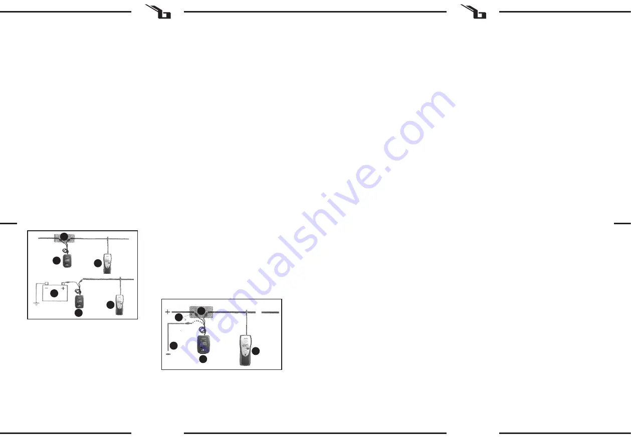
1.
Transmitter
2.
Receiver
3.
Fuse socket or plug
4.
Ground
5.
Transmitter connection method to choose
(depending on the wiring system)
f)
If, despite the correct connection of the device, the
receiver is unable to pick up any signal, increase the
sensitivity and try again.
g)
Make sure about the proper location of the break
found in the circuit by probing before and after the
break. If a gap is found, the beep will continue on
one side of the gap and will disappear on the other.
The place where the beep disappears is the place
where the circuit is broken.
h)
After you finish, disconnect the test lead clamps (7),
set the transmitter switch to the „OFF“ position (6)
and release the receiver „TEST“ button (5).
3.3.2 CABLE IDENTIFICATION
a)
Set the transmitter switch (6) to the „TONE“ position
(the red indicator light should come on if the battery
is in good working condition).
b)
Turn the receiver on by setting the sensitivity knob (4)
in the middle position. Carry out a short equipment
test by pressing and holding the „TEST“ button (5)
and at the same time bring the probe tip (1) near the
transmitter test lead (7). The receiver should catch
the signal and produce a sound - if so, it means that
the device is working properly.
c)
Connect the black test lead clamp (7) to the positive
circuit (or the negative circuit for vehicles with
a positive lead connected to the chassis). Then
connect the red clamp to the wire that will be traced
- a convenient place for this is a socket of a blown
fuse, plug, etc.
d)
Move the probe over all the wires until the sound
signal is the loudest. The wire that causes the
loudest signal is the one you want to identify. NOTE:
for a cable bundle or duct it may be necessary to
separate the cables to identify the correct one.
e)
After you finish, disconnect the test lead clamps (7),
set the transmitter switch to the „OFF“ position (6)
and release the receiver „TEST“ button (5).
3.3.7 WORK IN A NOISY ENVIRONMENT
If you operate in a loud environment that may interfere
with the assessment of the sound signal, it is recommended
to use headphones (not included with the device). The
receiver is equipped with a 3.5 mm jack input.
3.3.8 REPLACING THE BATTERY (IN TRANSMITTER OR
RECEIVER)
Loosen the screw on the back of the housing and remove
the cover. Disconnect the used battery from the connecting
clips. Connect the new battery, slide it into the bay, replace
the cover and tighten the screw.
3.4. CLEANING AND MAINTENANCE
a)
Store the unit in a dry, cool place, free from moisture
and direct exposure to sunlight.
b)
Do not spray the device with a water jet or submerge
it in water.
c)
Do not allow water to get inside the device through
vents in the housing of the device.
d)
Clean the vents with a brush and compressed air.
e)
Use a soft cloth for cleaning.
f)
Do not leave the battery in the device if it will not be
used for a longer period of time.
g)
Do not use sharp and/or metal objects for cleaning
(e.g. a wire brush or a metal spatula) because they
may damage the surface material of the appliance.
4
1
2
5
3
1.
Transmitter
2.
Receiver
3.
Fuse socket or plug
4.
Battery
d)
Set the receiver sensitivity knob (4) to the middle
position. Press and hold down the „TEST“ button (5)
and at the same time slowly bring the probe as close
as possible to the tested cable. The receiver probe
(1) should be located above or below the cable at an
angle of 90o to it.
e)
The receiver beeps as the cable is followed. If you
take the probe away from the wire, the beep will
get weaker until it disappears. If, despite the correct
connection of the device, the receiver is unable to
pick up any signal, increase the sensitivity and try
again.
1
2
3
4
1
2
3.2. PREPARING FOR USE
APPLIANCE LOCATION
The ambient temperature must not exceed 45°C and the
relative humidity should not exceed 85%. Keep the device
away from any hot surfaces.
3.3. DEVICE USE
3.3.1 USING PROBES
To get the best range of the receiver probe, place it above
or below the test lead and point at 90° to the lead.
3.3.2 SETTING THE SENSITIVITY LEVEL
To turn on the receiver or increase its sensitivity, turn the
sensitivity knob (4) clockwise. To turn off the receiver or
reduce its sensitivity, turn the knob counterclockwise.
3.3.3 TRACING CABLES
a)
Set the transmitter switch (6) to the „TONE“ position
(the red indicator light should come on if the battery
is in good working condition).
b)
Turn the receiver on by setting the sensitivity knob (4)
in the middle position. Carry out a short equipment
test by pressing and holding the „TEST“ button (5)
and at the same time bring the probe tip (1) near the
transmitter test lead (7). The receiver should catch
the signal and produce a sound - if so, it means that
the device is working properly.
c)
Connect the black test lead clamp (7) to the positive
circuit (or the negative circuit for vehicles with
a positive lead connected to the chassis). Then
connect the red clamp to the wire that will be traced
- a convenient place for this is a socket of a blown
fuse, plug, etc.
f)
After you finish, disconnect the test lead clamps (7),
set the transmitter switch to the „OFF“ position (6)
and release the receiver „TEST“ button (5).
3.3.4 CHECKING FOR SHORT CIRCUITS IN THE WIRING
SYSTEM
a)
Disconnect the power supply and all loads (e.g. lamp)
from the cable to be traced.
b)
Set the transmitter switch (6) to the „CONT“ position
and connect the test lead clamps to the pair of leads
to be checked.
c)
If the resistance is below 10 kΩ, the green „CONT“
indicator will light up. This means that this pair
of cables causes a short circuit If all loads have
previously been removed from the cable.
3.3.5 LOCATING AN OPEN CIRCUIT
a)
Set the transmitter switch (6) to the „TONE“ position
(the red indicator light should come on if the battery
is in good working condition).
b)
Turn the receiver on by setting the sensitivity knob (4)
in the middle position. Carry out a short equipment
test by pressing and holding the „TEST“ button (5)
and at the same time bring the probe tip (1) near the
transmitter test lead (7). The receiver should catch
the signal and produce a sound - if so, it means that
the device is working properly.
c)
Connect the black test lead clamp (7) to the positive
circuit (or the negative circuit for vehicles with
a positive lead connected to the chassis). Then
connect the red clamp to the wire that will be traced
- a convenient place for this is a socket of a blown
fuse, plug, etc.
d)
Set the receiver sensitivity knob (4) to the middle
position. Press and hold down the „TEST“ button (5)
and at the same time slowly bring the probe as close
as possible to the tested cable. The receiver probe
(1) should be located above or below the cable at an
angle of 90o to it.
e)
Move the probe along the cable or check in different
places. In each case start from the transmitter and
move slowly towards the load (an accessory, lights,
etc.) When the continuous beep of the receiver
disappears, it means the probe has passed an open,
broken or bad circuit connection.
h)
Do not clean the device with an acidic substance,
agents of medical purposes, thinners, fuel, oils or
other chemical substances because it may damage
the device.
SAFE REMOVAL OF BATTERIES AND RECHARGEABLE
BATTERIES
9V (6F22) batteries are installed in the devices. Remove
used batteries from the device using the same procedure
by which you installed them. Recycle batteries with the
appropriate organisation or company.
DISPOSING OF USED DEVICES
Do not dispose of this device in municipal waste systems.
Hand it over to an electric and electrical device recycling
and collection point. Check the symbol on the product,
instruction manual and packaging. The plastics used
to construct the device can be recycled in accordance
with their markings. By choosing to recycle you are
making a significant contribution to the protection of our
environment.
Contact local authorities for information on your local
recycling facility.
EN
EN


