background image

STEINDORFF

®


4.


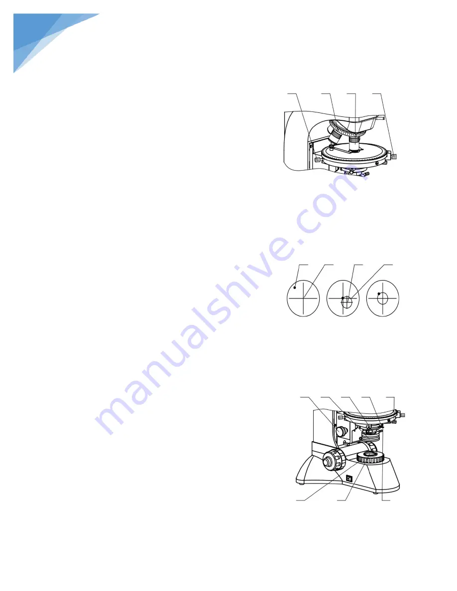
Rotatable Stage Controls, see Figure 5 

4.1.


Put a specimen on the stage, observe it using dividing 

eyepiece and 10X objective. 

4.2.


Search one target in field of view, adjust it to the center 

of view. See Figure 6 A. 

4.3.


Rotate the stage. If the stage out of center, the target 

will encircle the center of circle. See Figure 6 B. 

4.4.


To center the center of circle in the field of view. Use 

the two centering screws, the stage centering adjustment 

can be finished. See Figure 6 C. 

4.5.


If other objectives out of center, you may adjust it using 

the objective centering screws. 

4.6.


Tightening the stage setting screw can fix the rotatable 

stage. 

5.


Condenser Alignment Controls. 

5.1.


Condenser Components:

 The condenser is located 

below the stage, see Figure 7. Abbe condenser; its 

mounting ring with lock screw and two large centering 

screws at either side. The adjustment knob for raising 

and lowering the condenser. 

5.2.


Condenser Alignment

 – to center the abbe condenser 

in the optical light path. See Figure 8. 

a.


Turn the 10X objective to optics path, close iris 

diaphragm and lower the Abbe condenser until 

observe the image of iris diaphragm. 

b.


If the Abbe condenser optics axis offset optics 

system axis, the image of iris diaphragm is similar 

to figure 8A. The image may be out of focus and 

out of center. 

c.


Adjust the sub-stage adjustment knob until the side 

of image is clear. Adjust the Abbe condenser 

centering screw until the iris diaphragm locate in 

the center of field of view, see figure 8 B. 

d.


Open the iris diaphragm until the image is almost 

as large as the field of view, see figure 8 C. Raise 

Abbe condenser again for normal observe. 

5.3.


Figure 5 

1.


Stage Centering Screw 

2.


Objective Centering Screw 

3.


10X Objective 

4.


Stage Set Screw 

Figure 6 

1.


Target 

2.


Center of View 

3.


Center of Circle 

4.


Circle 


Figure 7 

1.


Sub-stage Adjustment Knob 

2.


Polarizer 

3.


Auxiliary  Lens 

4.


Condenser  Set Screw 

5.


Condenser  Centering  Screw 

6.


Collector 

7.


Filter Seat 

8.


Aperture Adjustment  Lever 


Summary of Contents for NYMCS-1500

Page 1: ...nt images please make a few trial snaps making sure you can operate the microscope properly 3 LCD screen was made by precision technology 99 99 of its pixels are up to specifications 0 01 of the pixel...

Page 2: ...Make sure the table is smooth horizontal and firm enough 3 When moving the instrument please use two hands to grip with the two sides of the microscope body 4 If the bacterium solution or the water s...

Page 3: ...Holder 7 Condenser with Aperture Diaphragm 8 Polarizer 9 Collector 10 Power Switch 11 Transmitted Reflection Illumination Toggle Switch 12 Fine Focus Control Knob 13 Coarse Focus Control 14 Focus Tens...

Page 4: ...h 25mm Field 18mm Stage Circular rotating stage Diameter 150mm 360 graduated in 1 increments minimum retardation resolution 6 center adjustable and locking clamp for stage rotation Condenser Strain fr...

Page 5: ...ected and the fuse holder located on the power Inlet 1 2 Press the power switch on the side of I which means the circuits is got through If the light does not appear to be ON check the brightness cont...

Page 6: ...ntact the stage or slide glass when using the microscope Its use also simplifies focusing After focusing on the slide glass with the coarse adjustment rotation of the lever toward the rear of the micr...

Page 7: ...denser 5 2 Condenser Alignment to center the abbe condenser in the optical light path See Figure 8 a Turn the 10X objective to optics path close iris diaphragm and lower the Abbe condenser until obser...

Page 8: ...ensator to light path 6 3 The push rod to the upper left of the trinocular head will send 100 of the image light to the binocular eyepieces or to the top port It satisfy high grape photography NOTE If...

Page 9: ...e adjusted slightly to change contrast 2 To center the incident or vertical lamp a Put a piece of paper and place it on the stage Take out one objective form nosepiece and rotate the nosepiece until t...

Page 10: ...r and ground glass you may turn anyone to the light path to obtain an image of good quality 3 2 Changing the Light Bulb and the Fuse 1 Changing the lamp of the vertical illuminator See figure a Discon...

Page 11: ...nstalling the new lamp be careful not to touch the glass with your fingers The new lamp should be supplied in a plastic protective envelope If not use a tissue or other medium to grasp the lamp This w...

Page 12: ...ons 1 Crosshair Coordinate 2 Color White Black Red Purple Green 3 Direction key 4 Menu Setting Exit 5 Display button Only display image and remove kinds of characters symbols 6 Confirm Button 7 Snapsh...

Page 13: ...r 3 seconds the microscope system will be in the preview in the real time automatically when you can snap C Adjust microscope s definition according to its imaging focal length make images sharp from...

Page 14: ...tion key allows you to choose the following functions A Resolution B Camera function setting C Display setting On the snap model press menu button to enter menu interface Use direction key to select a...

Page 15: ...you press MENU button again the model comes back to snap model 2 Video Resolution Select video resolution On video model press MENU button as shown the Resolution 1080P30 1080P30 means the pixels has...

Page 16: ...own key to select as Scene WB DE Contrast Sharpness AE Meter AE ISO AE Bias Fig 29 30 For example Fig 29 you can press the OK key to enter the Scene setting and choose by up down keys Fig 31 Press OK...

Page 17: ...Fig 33 You can press the OK key to enter the Date Time setting and change by direction keys Fig 34 Press OK button again to save your selection or exit by MENU button Once confirmed the model comes ba...

Page 18: ...17 STEINDORFF B WB White Balance WB will help you to obtain superb color when observing C DE Color effects D Sharpness SET EXIT SET SET EXIT EXIT...

Page 19: ...18 STEINDORFF E AE Meter F AE ISO G AE Bias SET EXIT SET EXIT SET EXIT...

Page 20: ...ou can save the time B Display Date and time information can be stored together with photo taken in SD card File names also contain date and time information Before using this camera please set the da...

Page 21: ...he SD card inserted Attention Even the protected content will be deleted when formatting cannot be resumed again Select No and press menu button the model comes back to the snap mode D Reset system se...

Page 22: ...21 STEINDORFF F Language We developed 9 languages according to your demand G Beep H USB Selection SET EXIT SET SET EXIT EXIT...

Page 23: ...een will show Card full B Record When you turn on the microscope you can press button to record When the card is full the LCD screen will show Card full C Playback Press button to select playback mode...

Page 24: ...th aviation gasoline is recommended Do not use organic solvents such as alcohol ether or other thinner etc for cleaning the pointed parts or plastic components 3 Avoid disassembling the microscope Bei...

Reviews: