background image

www.autani.com

www.autani.com

8

9

  Mounting

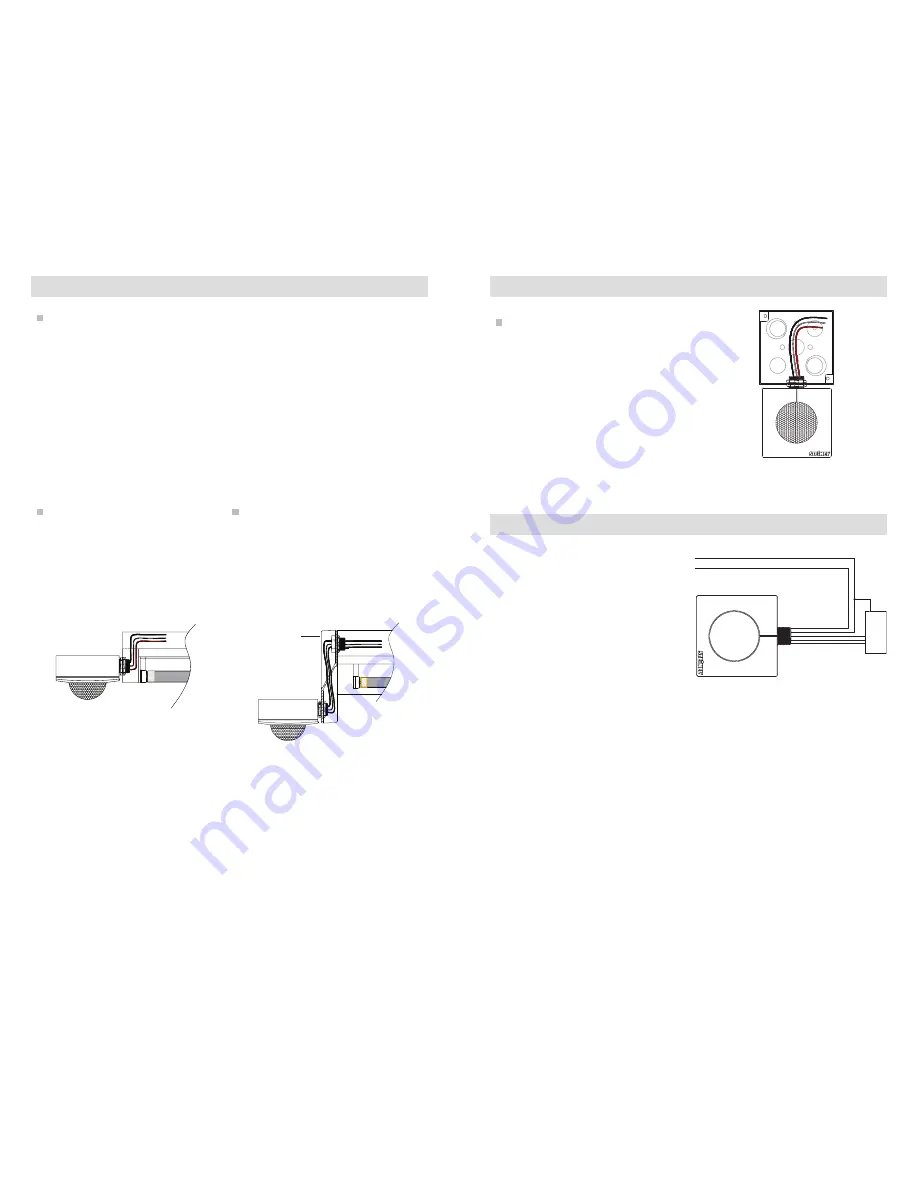
End of fixture mounting - 

HBS 300, HBS 200

EM 1 Extender Module

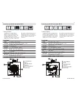
Placement guidelines - HBS 300, HBS 200

The HBS 300 and HBS 200 typically 

mount to a 1/2” knockout at the end of a 

high/low bay lighting fixture. The sensor’s 

lens should be mounted below the 

bottom edge of the fixture.  

The EM 1 Extender Module is 

recommended for use with the HBS 300 

and HBS 200 if the knockout at the end 

of the fixture is located greater than 1/2” 

from the bottom edge of the fixture.  

HBS Sensor

Fixture

•  Sensor module mounts to a 1/2” 

knockout of a lighting fixture or    

junction box.

•  Detection lens must have a clear, 

unobstructed view of controlled area 

and must project beyond the lamps.

•  Sensor should be 6 to 8 feet away from 

heating/cooling supply ducts.

•  Ideal mounting height is up to 45 feet.
•  Must be mounted on a stable platform.

EM 1

Fixture

HBS Sensor

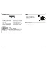
Junction box mounting - HBS 300, 

HBS 200

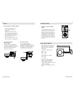
  Wiring - HBS 300, HBS 200

When installing, make sure power has 

been switched off at the breaker and 

check that the circuit is dead with a 

voltage tester.
The leads consist of three wires:
Black  = line
White  = neutral 
Red  = load 
When the HBS-DC is installed:
Violet  = DIM +
Gray  = DIM -
If in doubt, identify the individual 

conductors with a voltage tester or 

contact a qualified electrician.
Note 1: Dimming wires are only available 

with HBS-DC installed.
Note 2: All HBS and HBS-DC are Class 1 

rated.

If mounting to the end of a fixture is not 

possible, the HBS 300, HBS 200 can be 

mounted to any junction box with a 1/2” 

(trade size) knockout. With the HBS 300 

and HBS 200, this may be necessary if 

the fixture location has an obstruction 

that would block the view of the sensor 

(for example: racking is directly beneath 

the fixture).

Junction 

box

HBS 300, HBS 200

HBS 300, HBS 200

LINE (BLACK)

NEUTRAL (WHITE)

NEUTRAL
HOT

LOAD (RED)

DIM + (VIOLET)

DIM – (GRAY)

LOAD

DRIVER

  Mounting (continued)

Summary of Contents for HBS 200

Page 1: ...RoHS Compliant HBS DC HBS 300 HBS 200 HBS 200 HBS 300 HBS DC Installation Instructions Wireless High Bay Controls English I o T E N A B L ED BY ...

Page 2: ...bay aisle ways where aisle coverage and wireless control is desired Package Contents Installation Overview WARNING Turn power off at the circuit breaker before installing the sensor Sensor must be installed and used in accordance with appropriate electrical codes and regulations Installation by a qualified electrician is recommended Communication Frequency Transmission Range 2 4 GHz 600 ft 182 8 m...

Page 3: ... 62 in 15 75 mm Product description Product description Specifications Specifications The HBS 200 High Bay Occupancy Sensor provides occupancy based lighting control in high bay applications and communicates wirelessly to other devices to create groups lighting zones The sensor contains two dual element pyroelectric detectors and is engineered to perform at a wide range of mounting heights up to 4...

Page 4: ...just snaps into the connection terminal No tools are required This sensor is commissioned remotely through the EnergyCenter software Product description The HBS DC Wireless Control Module works with STEINEL s HBS 200 and HBS 300 wireless lighting control devices to create control zones without the need for additional wiring The HBS DC typically comes preinstalled in the STEINEL wireless device Dev...

Page 5: ... on a stable platform EM 1 Fixture HBS Sensor Junction box mounting HBS 300 HBS 200 Wiring HBS 300 HBS 200 When installing make sure power has been switched off at the breaker and check that the circuit is dead with a voltage tester The leads consist of three wires Black line White neutral Red load When the HBS DC is installed Violet DIM Gray DIM If in doubt identify the individual conductors with...

Page 6: ... load will turn ON for up to one minute If no motion is detected the load will switch OFF If motion is detected and the target light level setting is less than the daylight level the load will stay ON for the selected time delay setting per DIP switch setting If the daylight level at power up is greater than the target light level setting the load will switch OFF regardless of occupancy Surge prot...

Page 7: ...200 can be rotated 90 degrees To do this remove the sensor housing from the back box by pressing the tabs on either side of the sensor Coverage may vary depending on mounting height and environmental conditions 10 20 30 40 LC3 40 ft 50 50 40 40 35 ft 22 ft 22 ft 35 ft 10 20 30 40 Aisle LC3 radial tangential 40 ft 13 ft 50 ft 53 ft 53 ft 50 ft Setup Commissioning Lens Covers Lens covers can be used...

Page 8: ...pment should be installed and operated with a minimum distance of 20 centimeters between the radiator and your body Troubleshooting Wireless communication troubleshooting Is the receiver device too far away from the transmitting device resulting in too weak of a signal at the receiver See Transmission Range on page 3 Can the radio signal leave the transmitter and reach the receiver or is it inhibi...

Page 9: ...1 Lyndale Avenue South USA Bloomington MN 55420 Tel 1 952 888 5950 Fax 1 952 888 5132 www steinel net Autani LLC 7090 Columbia Gateway Drive Suite 140 Columbia MD 21046 Tel 1 443 320 2233 www autani com I o T E N A B L ED BY ...

Reviews: