10
ZTM 1250
ZTM 1250
ZTM 1250
ZTM 1250
ZTM 1250
MAINTENANCE
HYDRAULIC SYSTEM
Check fluid level in the hydraulic system every 100
hours or when a leak has occurred. If the fluid is
low, check all components for leaks.
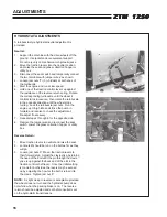
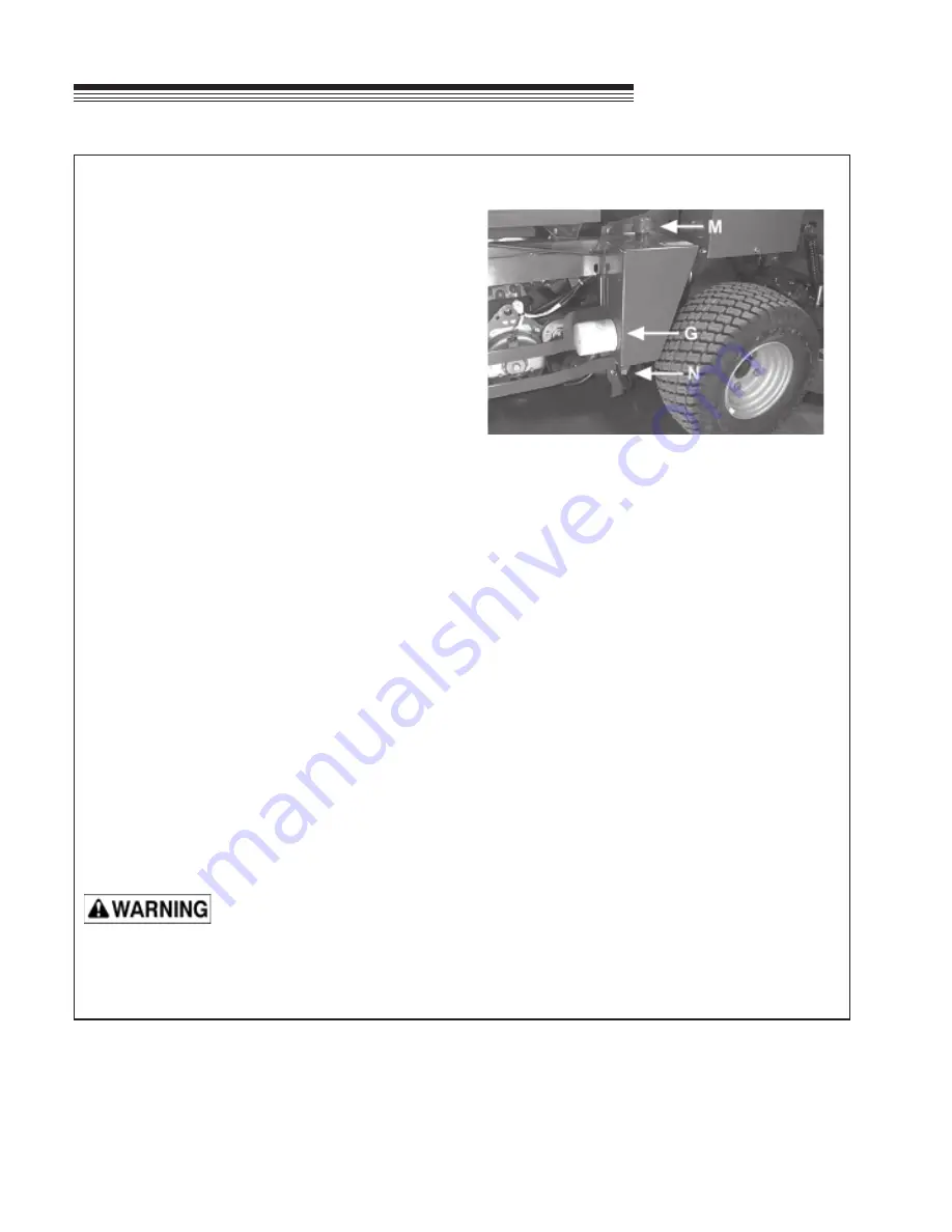
To check, remove reservoir cap
M
. The fluid level
should be at the bottom of the filler tube. If low, top up
(do not overfill). Use one of the oils listed below:
–
SAE 15W40 motor oil
–
SAE 20W50 motor oil
–
15W50 synthetic motor oil
AFTER FIRST FIVE (5) HOURS
1. Remove plug
N
to drain hydraulic reservoir.
Dispose of used oil in accordance with local
requirements.
2. Clean and replace the plug.
3. Change hydraulic oil filter
G
.
4. Fill the reservoir with fresh oil to the bottom of the
reservoir filler tube, using an oil from the list
above. Do not overfill.
PERIODIC OIL CHANGES
Change the hydraulic fluid and hydraulic filter after
each 500 hours of operation using the same
procedure given above.
NOTES:
Before servicing the hydraulic system, stop the engine, disconnect spark plug wires and disengage the PTO.
–
After any hydraulic line is opened, plug or cap it promptly to reduce the risk of contamination.
–
Do not use teflon tape on hydraulic pipe fittings. Use a liquid sealant that will dissolve into the system.
–
Make sure all hydraulic connections are tight and hydraulic hoses and lines are in good condition before
applying pressure to system.
The machine's hydraulic system operates under high pressure. When checking for leaks, do not use your
hands to attempt to find a leak. Instead, use cardboard or paper. Escaping hydraulic fluid can be under
sufficient pressure to penetrate skin and cause serious injury. If hydraulic fluid is injected into the skin, it
must be promptly removed by a doctor familiar with this form of injury or gangrene may result.
View from right side
Summary of Contents for 442105
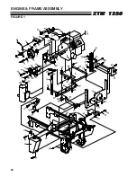
Page 26: ...24 ZTM 1250 ZTM 1250 ZTM 1250 ZTM 1250 ZTM 1250 ENGINE FRAME ASSEMBLY FIGURE 1 ...
Page 28: ...26 ZTM 1250 ZTM 1250 ZTM 1250 ZTM 1250 ZTM 1250 WHEELS BRAKES FIGURE 2 ...
Page 30: ...28 ZTM 1250 ZTM 1250 ZTM 1250 ZTM 1250 ZTM 1250 FRONT PANEL PUSH ARMS FIGURE 3 ...
Page 32: ...30 ZTM 1250 ZTM 1250 ZTM 1250 ZTM 1250 ZTM 1250 PUMPS CONTROL PANEL FIGURE 4 ...
Page 34: ...32 ZTM 1250 ZTM 1250 ZTM 1250 ZTM 1250 ZTM 1250 BLOWER FUEL TANK FIGURE 5 ...
Page 36: ...34 ZTM 1250 ZTM 1250 ZTM 1250 ZTM 1250 ZTM 1250 BELTS FIGURE 6 ...
Page 38: ...36 ZTM 1250 ZTM 1250 ZTM 1250 ZTM 1250 ZTM 1250 BUMPER GRASSBOX FRAME FIGURE 7 ...
Page 40: ...38 ZTM 1250 ZTM 1250 ZTM 1250 ZTM 1250 ZTM 1250 HEAVY DUTY AIR CLEANER FIGURE 8 ...
Page 42: ...40 ZTM 1250 ZTM 1250 ZTM 1250 ZTM 1250 ZTM 1250 GRASSBOX FIGURE 9 ...
Page 44: ...42 ZTM 1250 ZTM 1250 ZTM 1250 ZTM 1250 ZTM 1250 ELECTRICAL FIGURE 10 ...
Page 46: ...44 ZTM 1250 ZTM 1250 ZTM 1250 ZTM 1250 ZTM 1250 HYDRAULICS FIGURE 11 ...
Page 48: ...46 ZTM 1250 ZTM 1250 ZTM 1250 ZTM 1250 ZTM 1250 SEAT ASSEMBLY FIGURE 12 ...
Page 50: ...48 ZTM 1250 ZTM 1250 ZTM 1250 ZTM 1250 ZTM 1250 DECALS FIGURE 13 ...
Page 52: ...50 ZTM 1250 ZTM 1250 ZTM 1250 ZTM 1250 ZTM 1250 OPTIONAL FILL INDICATOR 970145 FIGURE 14 ...
Page 54: ...52 ZTM 1250 ZTM 1250 ZTM 1250 ZTM 1250 ZTM 1250 HYDROGEAR PUMP FIGURE 15 ...
Page 56: ...54 ZTM 1250 ZTM 1250 ZTM 1250 ZTM 1250 ZTM 1250 BRAKE ASSEMBLY FIGURE 16 ...


