19
ZTM 1250
ZTM 1250
ZTM 1250
ZTM 1250
ZTM 1250
BELT REPLACEMENT
CUTTERDECK-TIMING BELT
1. Raise the foot plate on the cutterdeck.
2. Back off nut
N
to allow for removal of timing belt.
3. Loosen the three bolts
B
locking the timing belt
idler in place.
4. Install an extension on a 3/8” drive ratchet.
Insert it in the square hole of the timing belt idler
arm and use the ratchet handle to rotate the idler
enough to remove the belt from the idler and
drive sprockets.
When handling timing belts, take care not to twist or
bend them severely. Mishandling timing belts can
break the cords in them and lead to premature failure.
5. Install the new timing belt on the sprockets.
Line up the drive sprockets so the timing
marks
T
areat 90 degrees to each other. This
puts the blades at 90 degrees to each other as
well.
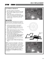
6. Tighten nut
N
until the bottom of the nut is aligned
with the notch in the bracket as shown.
7. Lock the idler in place by tightening nuts
B
.
8. Start the engine and operate the deck for a few
minutes to allow the belt to run in.
9. Loosen the locking nuts
B
and allow the spring to
take up the slack.
DO NOT OVER TENSION
.
The spring will supply the correct amount of
tension as long as the idler arm is free to rotate.
Lock the idler down.
10. Check the belt after the first several hours of
operation for slack. If there is any slack, repeat
step 9.
NOTE:
Timing belts use fiberglass or Aramid fiber
cords which have very little stretch. Once properly
tensioned, no further adjustment is usually neces-
sary. It is important that there be no slack in the belt,
because any slack can allow the belt to jump teeth
on the sprockets and get the blades out of time.
Since there is no stretch in the belt, it can easily be
over tightened. The spring allows the correct
amount of tension to be applied without danger of
over tension.
T
Alignment
Notch
Summary of Contents for 442105
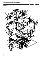
Page 26: ...24 ZTM 1250 ZTM 1250 ZTM 1250 ZTM 1250 ZTM 1250 ENGINE FRAME ASSEMBLY FIGURE 1 ...
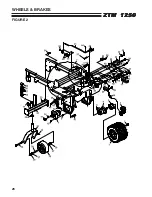
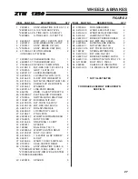
Page 28: ...26 ZTM 1250 ZTM 1250 ZTM 1250 ZTM 1250 ZTM 1250 WHEELS BRAKES FIGURE 2 ...
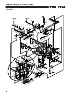
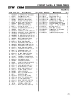
Page 30: ...28 ZTM 1250 ZTM 1250 ZTM 1250 ZTM 1250 ZTM 1250 FRONT PANEL PUSH ARMS FIGURE 3 ...
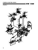
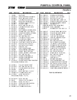
Page 32: ...30 ZTM 1250 ZTM 1250 ZTM 1250 ZTM 1250 ZTM 1250 PUMPS CONTROL PANEL FIGURE 4 ...
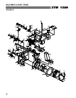
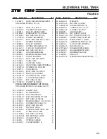
Page 34: ...32 ZTM 1250 ZTM 1250 ZTM 1250 ZTM 1250 ZTM 1250 BLOWER FUEL TANK FIGURE 5 ...
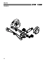
Page 36: ...34 ZTM 1250 ZTM 1250 ZTM 1250 ZTM 1250 ZTM 1250 BELTS FIGURE 6 ...
Page 38: ...36 ZTM 1250 ZTM 1250 ZTM 1250 ZTM 1250 ZTM 1250 BUMPER GRASSBOX FRAME FIGURE 7 ...
Page 40: ...38 ZTM 1250 ZTM 1250 ZTM 1250 ZTM 1250 ZTM 1250 HEAVY DUTY AIR CLEANER FIGURE 8 ...
Page 42: ...40 ZTM 1250 ZTM 1250 ZTM 1250 ZTM 1250 ZTM 1250 GRASSBOX FIGURE 9 ...
Page 44: ...42 ZTM 1250 ZTM 1250 ZTM 1250 ZTM 1250 ZTM 1250 ELECTRICAL FIGURE 10 ...
Page 46: ...44 ZTM 1250 ZTM 1250 ZTM 1250 ZTM 1250 ZTM 1250 HYDRAULICS FIGURE 11 ...
Page 48: ...46 ZTM 1250 ZTM 1250 ZTM 1250 ZTM 1250 ZTM 1250 SEAT ASSEMBLY FIGURE 12 ...
Page 50: ...48 ZTM 1250 ZTM 1250 ZTM 1250 ZTM 1250 ZTM 1250 DECALS FIGURE 13 ...
Page 52: ...50 ZTM 1250 ZTM 1250 ZTM 1250 ZTM 1250 ZTM 1250 OPTIONAL FILL INDICATOR 970145 FIGURE 14 ...
Page 54: ...52 ZTM 1250 ZTM 1250 ZTM 1250 ZTM 1250 ZTM 1250 HYDROGEAR PUMP FIGURE 15 ...
Page 56: ...54 ZTM 1250 ZTM 1250 ZTM 1250 ZTM 1250 ZTM 1250 BRAKE ASSEMBLY FIGURE 16 ...


