8
CAB
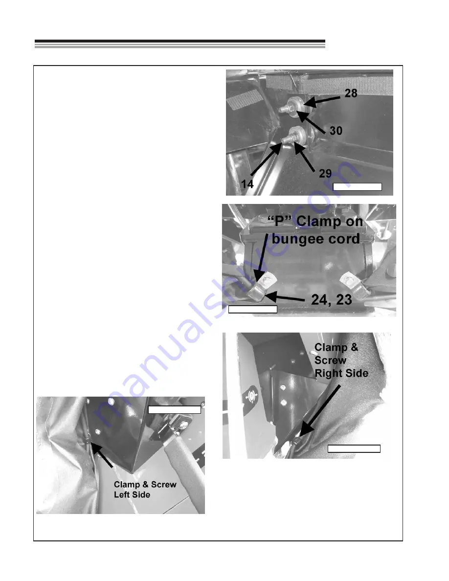
21. Install the rubber isolators
(Item 28)
onto the
rear mount bracket. Secure the rear mounting
bracket to the back of the cab using hardware:
Figure 17
(4) 3/8" X 2.50" long bolt
(Item 14)
(4) 3/8" nylock nuts
(Item 29)
(4) 3/8" flat washers
(Item 30)
Torque to 30 ft-lb (41 N-m)
22. Tighten the nuts on the U-bolts for the rear mount
installed in Step 17.
23. Attach the two "P" clamps supplied on the 96"
bungee cord to the machine at the foot panel
using hardware:
Figure 18
(2) .75" long bolts
(Item 24)
(2) 1/4" flanged nuts
(Item 23)
24. Remove screws
(Item 27 )
from "P" clamps
(Item 30)
on each side that were attached to
the front filler panels in Steps 13 and 14. Slide
bungee cord into the clamp and attach bolt and
clamp to front filler panels as shown in
Figure 19
& 20
FIGURE 17
FIGURE 18
FIGURE 19
FIGURE 20
ASSEMBLY
Summary of Contents for 75-71215B4
Page 13: ...11 CAB PARTS SECTION ...


