4
CAB
FRONT MOUNT INSTALLATION:
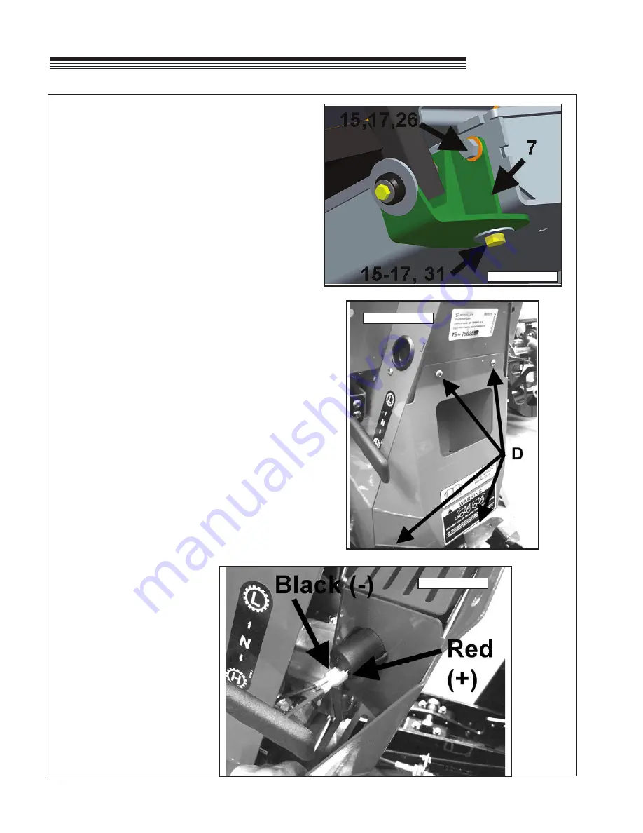
5. Secure the two front mount brackets
(Item 7)
to the bottom of the machine using hardware.
Torque to 70 ft-lb (95n-m).
Figure 4
(2) 1/2" X 1.50" long bolts
(Item 16)
(2) 1/2" nylon nuts
(Item 17)
(3) 1/2" large OD flat washers
(Item 31)
two on right side one on outside left side
(1) 1/2" small OD flat washer
(Item 15)
one on inside left side.
6. Secure the brackets to the side of the machine
using hardware. Torque to 70 ft-lb (95n-m).
Figure 4
(4) 1/2" x 1.25 long bolts
(Item 26)
(4) 1/2" nylon nuts
(Item 17)
(4) 1/2" small OD flat washers
(Item 15)
7. Reinstall the floor plate with hardware removed in
Step 4.
8. Reattach the reverse control pedal using
hardware removed in Step 3.
PUMP COVER FILLER PANEL INSTALLATION:
9. Remove the four mounting screws
D
securing the
rear pump cover on the steering tower. Unplug
the two wires from the accessory plug in the
pump cover storage area.
NOTE
the polarity of
the connections.
Figure 5 & 6
FIGURE 5
FIGURE 6
FIGURE 4
ASSEMBLY
Summary of Contents for 75-71215B4
Page 13: ...11 CAB PARTS SECTION ...


