background image

3/96

1 - 2

09-282C

INTRODUCTION

section 1

Specification

Overall width _ _ _ _ _ _ _ _ _ _ _ _ _ _ _ _ 35-5/8"
Overall height _ _ _ _ _ _ _ _ _ _ _ _ _ _ _ 44-1/2"
Overall length _ _ _ _ _ _ _ _ _ _ _ _ _ _ _ 53-1/4"
Chipper Knives _ _ _ _ _ _ _ _ _ _ _ _ _ _ _ 4 hardened
Shredder Sections _ _ _ _ _ _ _ _ _ _ _ _ _ 72 hardened
Rotor Diameter _ _ _ _ _ _ _ _ _ _ _ _ _ _ _ 18"
Rotor Width _ _ _ _ _ _ _ _ _ _ _ _ _ _ _ _ 12"
Rotor Speed (maximum) _ _ _ _ _ _ _ _ _ _ _ 1550 RPM
Shredder Throat Opening _ _ _ _ _ _ _ _ _ _ 9-1/2" x 11"
Maximum material size for Shredder _ _ _ _ _ _ 1-1/2" diameter x 24" long
Maximum material size for Chipper

_ _ _ _ _ _ 4" diameter

Application

_ _ _ _ _ _ _ _ _ _ _ _ _ _ _ _ Steiner 420, 425, 525

Power Units only

Weight _ _ _ _ _ _ _ _ _ _ _ _ _ _ _ _ _ _ 430 lbs.

Specifications are subject to change without notice.

Summary of Contents for CS312

Page 1: ...2C CHIPPER SHREDDER Model CS312 Starting Serial No 1001 CHIPPER SHREDDER BLOWER Model CS313 Starting Serial No 1001 CAUTION Avoid injuries Read and understand Operator s manual before operating tractor or equipment It contains instructions for safe operation ...

Page 2: ...RESULT IN INJURY TO YOU OR OTHERS BE SURE MACHINE IS IN SAFE OPERATING CONDITION BEFORE USE INSPECT MACHINE DAILY REPLACE ALL WORN OR DAMAGED PARTS KEEP ALL GUARDS AND SHIELDS IN PLACE CHECK OPERATION OF ALL SAFETY INTERLOCK SWITCHES DAILY DO NOT OVERRIDE INTERLOCK SYSTEM IT IS FOR YOUR PROTECTION DO NOT ALLOW MINORS OR THE INEXPERIENCED TO OPERATE MACHINE KEEP PEOPLE AND PETS A SAFE DISTANCE AWAY...

Page 3: ... INSTALLATION SECTION 3 Mounting Instructions 3 1 OPERATION SECTION 4 Operating Precautions 4 1 Operating Instructions 4 1 Shredding Chipping Stopping Instructions 4 2 SERVICE SECTION 5 Service Schedule 5 1 Adjustments 5 2 Trouble Shooting Chart 5 4 PARTS SECTION 6 Parts List and Illustrations Index 6 1 ASSEMBLY SECTION 7 Assembly Instructions 7 1 WARRANTY last page ...

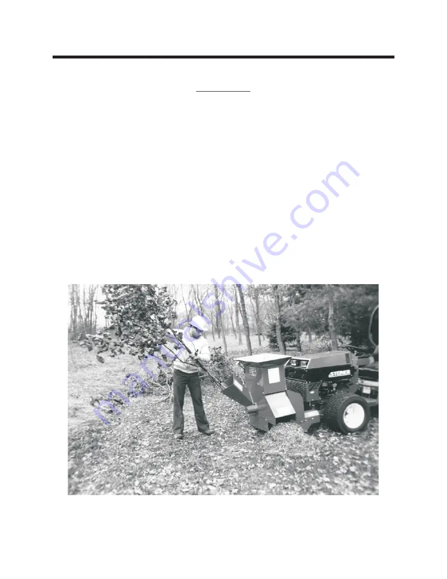
Page 4: ...n debris cornstalks plants prunings vines etc can easily be processed through the shredder inlet Sticks and branches should be limited to 1 1 2 inches in di ameter and no longer than 24 inches to avoid excess whipping and wrapping The processed material can be placed in a compost pile or spread on the ground as mulch giving a professionally landscaped look The chipper inlet can chip branches up to...

Page 5: ...dened Rotor Diameter _ _ _ _ _ _ _ _ _ _ _ _ _ _ _ 18 Rotor Width _ _ _ _ _ _ _ _ _ _ _ _ _ _ _ _ 12 Rotor Speed maximum _ _ _ _ _ _ _ _ _ _ _ 1550 RPM Shredder Throat Opening _ _ _ _ _ _ _ _ _ _ 9 1 2 x 11 Maximum material size for Shredder _ _ _ _ _ _ 1 1 2 diameter x 24 long Maximum material size for Chipper _ _ _ _ _ _ 4 diameter Application _ _ _ _ _ _ _ _ _ _ _ _ _ _ _ _ Steiner 420 425 525 ...

Page 6: ...nderstand the owner s manual before attempting to operate this machine 2 Operate all controls from the operator s seat NO RIDERS 3 Keep all shields in place and safety switches adjusted properly 4 Do not leave equipment unattended STOP the engine and remove the key 5 Do not allow minors or the inexperienced to operate this machine 6 Keep people and pets a safe distance away from machine using powe...

Page 7: ...te machine on a paved concrete or hard gravel surface Dis charged material may rebound 6 Emergency stop switch must have cable plugged into outlet on power unit Do not operate machine without this emergency stop switch connected 7 When feeding shreddable material into the machine be extremely careful that pieces of metal rocks bottles cans or other foreign objects are not fed into the feeding cham...

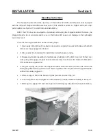
Page 8: ...ligning the quick hitch Be sure that both latches are fully engaged and locked 2 Stop engine Do not attempt to install drive belt with engine running 3 Release double idler assembly to facilitate easy installation of the B 41 drive belt Put belt over drive pulley and engage or adjust double idler assembly See Power Unit Operator s Manual for PTO belt tension adjustment 4 Plug emergency stop cable ...

Page 9: ...he parking brake on the tractor Do not operate the chipper shredder on a paved concrete or hard gravel surface Discharged material may rebound Lower machine before operating Do not operate in transport position 5 Before starting the machine make sure the cutting chamber is empty 6 When feeding shreddable material into the machine be extremely careful that pieces of metal rocks bottles cans or othe...

Page 10: ...irst into the chipper chute until it contacts the chipper blades The actual feed rate of the limb into the chipper will depend on the type of material fed and sharpness of the cutting blades Alternately insert and retract the limb or insert continuously at a rate that will not stall the tractor Rotating the branch as it is fed will improve cutting action The chipping knives will dull with use and ...

Page 11: ... belt shields and check drive belts for wear or cracking Replace if worn See Section 5 3 Grease rotor bearings and drive shaft bearings 100 Hour or Annual Remove discharge shield and discharge screen and check rotor Inspect chipper knives and shredder sections for wear Replace worn parts for efficient operation See Page 5 2 5 3 Storage Thoroughly clean the machine and store in a dry place to preve...

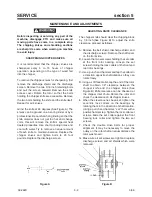
Page 12: ...n bolts to 20 foot pounds Replace the discharge screen ADJUSTING KNIFE CLEARANCE The chipper knife should clear the chipping block by 1 8 inch See Figure B To adjust the knife clearance proceed as follows A Remove the belt shield discharge shield and the discharge screen Remove the shaft cover on the front side B Loosen the two set screws holding the set collar at the front rotor bearing Loosen th...

Page 13: ...arge shield CLEANING PLUGGED ROTOR If too large of material or too much material is fed into the chipper shredder it may become plugged To clear plugged rotor proceed as follows A Disengage PTO and stop engine B Remove discharge shield and discharge screen C Clean debris out of the shredding rotor Turn the rotor by hand to be sure it is free to rotate D Replace discharge screen and discharge shiel...

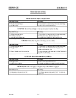
Page 14: ...ection 5 2 SYMPTOM Shredder requires excessive power or stalls Possible Cause Remedy 1 Obstructed discharge 2 Plugged rotor 3 Green material will not discharge 1 Use branch or similar object to clear discharge 2 Clear rotor feed material into hopper more slowly See Section 5 3 3 Alternately feed dry material or allow material to dry before shredding SYMPTOM Drive belts squealing or smoking Possibl...

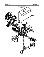
Page 15: ...Parts Figure 1 6 2 Frame Parts Figure 2 6 4 Emergency Stop Switch Parts Figure 3 6 6 Chipper Shredder Blower Parts Figure 4 6 8 ALWAYS GIVE MODEL AND SERIAL NUMBER WHEN ORDERING SERVICE PARTS Model CS312 begins with Serial Number 1001 Model CS313 begins with Serial Number 1001 ...

Page 16: ...rev 8 98 6 2 09 282C PARTS section 6 Hitch and Drive Parts Figure 1 ...

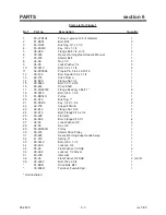
Page 17: ... 1 16 80 244 Drive Shaft 1 17 55 FB23016 Flange Bearing 2 Bolt 1 2 18 90 0610 Bolt 3 8 X 1 1 4 4 19 83 BK52H Pulley 1 20 83 H16 Bushing 1 2 21 85 K0410 Key 1 4 X 1 1 4 2 22 62 758 Support Stand 1 23 99 E12 Flange Nut 5 16 5 24 99 K19 Bolt Flange 5 16 x 3 4 1 25 83 028 Flat Idler 1 26 99 K02 Bolt Flange 5 16 X 1 4 27 96 06 Lock Washer 3 8 6 28 92 06 Nut 3 8 7 29 83 2BK50H Pulley 1 30 60 575 Shield ...

Page 18: ...rev 5 00 6 4 09 282C PARTS section 6 Frame Parts Figure 2 ...

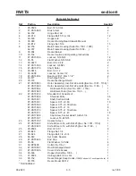
Page 19: ...incl Ref 22 and 24 Ser No 1160 1 87 CS70584 Weldment Rotor Ser No 1001 1159 1 87 CS72689 Weldment Rotor Ser No 1160 1 22 87 CS70972 Shredder Kit Consists of 1 87 CS70856 Shredder Knife 36 87 CS70381 Shaft Section Knife 6 87 CS70367 Spacer 0 75 x 0 59 10 87 CS70368 Spacer 0 75 x 0 59 w hole 2 87 CS70369 Spacer 0 75 x 1 18 8 87 CS70370 Spacer 0 75 x 1 18 w hole 4 87 CS70371 Spacer 0 75 x 1 47 18 87 ...

Page 20: ...rev 8 98 6 6 09 282C PARTS section 6 Emergency Stop Switch Parts Figure 3 ...

Page 21: ...Switch Push Pull 1 7 11 016 Wire Clip 13 32 2 8 30 173 Cable 3 wire Switch to Plug 60 1 9 30 163 Connector Plug 4 pole 1 10 30 164 Connector Socket 4 pole 1 11 64 733 Mounting Bracket Electrical Socket 1 12 30 174 Wiring Harness All Model 420 425 w o electric clutch 1 30 175 Wiring Harness Model 425 with electric clutch 1 30 187 Wiring Harness Model 525 with electric clutch 1 13 30 112 Connector f...

Page 22: ...rev 5 00 6 8 09 282C PARTS section 6 MODEL CS313 Chipper Shredder Blower Parts Figure 4 ...

Page 23: ...16 X 3 4 10 15 00 002 Decal Steiner Small 1 16 00 138 Decal Danger Rotating Blades 1 17 87 CS15402 Speed Nut 5 16 4 18 87 CS17692 Spring Extension 3 4 OD 1 19 87 CS69126 Spacer Idler Pivot 1 20 87 CS15060 Carriage Bolt 3 8 x 2 1 21 87 CS70475 Idler Plate Blower 1 22 87 CS17740 Pulley Idler 3 1 2 1 23 87 CS15388 Locknut 3 8 NYL 1 24 87 CS17831 Bearing 1 Flushmount 3 Bolt 2 25 87 CS15391 Key Square ...

Page 24: ...ch out for normal operation Start engine and engage the PTO Push in for emergency stop Model 420 Serial No 3000 1 Disconnect the battery ground cable 2 On model 420 with Onan engine mount the electrical outlet on the left side of the black upper grille panel with two 1 4 x 3 4 flange bolts and nuts Choose a location using the existing slots in the panel On models with Kubota engines the outlets ar...

Page 25: ...cy stop switch as a PTO operational switch To restart disengage tractor PTO switch pull emergency knob OUT and engage PTO in the normal manner Model 425 Tractors without electric clutch 1 Disconnect the battery ground cable 2 Mount the Electrical outlet on the right side of the black upper grille panel with two 1 4 x 3 4 flange bolts and nuts Choose a location using the existing slots in the panel...

Page 26: ... with each Chipper Shredder to adapt to the following tractors Model 420 and 425 Tractors without electric clutch Part No Description 30 174 Harness with 44 black and brown wires and 20 white wire Model 425 Tractors with electric clutch Part No Description 30 175 Harness with 33 black and brown wires and 57 white wire ...

Page 27: ...ullet connector of the blue wire that goes to the front lift limit switch 6 Route the blue wire from the new harness to the PTO switch Find the PTO switch terminal with the blue wire attached Remove the wire and place the double male spade adapter on the switch Replace the wire and connect the new blue wire to the other terminal of the double spade 7 Check the wiring diagram and snap the 5 inch br...

Page 28: ...ay relay Either gray wire can be used 8 Install the other gray wire from the new harness 30 301 into the new relay plug so that it will connect with the 30 terminal of the new relay 9 Install the supplied black wire approx 11 long to the new relay plug so that it will connect with the 85 terminal of the new relay Install the eyelet end to the ground bolt on the dash Also install the black wire fro...

Page 29: ...s time 5 Install belt onto the inside groove on the rotor shaft pulley and onto the blower pulley Idler should run on the inside of belt for correct tension See Photo 1 Align pulleys to within 1 16 Tighten all pulleys on shafts 6 Install belt guard support bracket Fig 4 Ref 33 onto top 1 2 bolt for bearing on main frame and secure with 1 2 lock nut Fig 4 Ref 32 7 Install belt guard Fig 4 Ref 27 wi...

Page 30: ......

Reviews: