background image

STEL s.r.l. – Via del Progresso n° 59 – 36020 

Loc. Castegnero (VICENZA) - ITALY 

TEL. +39 444 639525 (central.) – +39 444 639682 (comm.) 

FAX +39 444 639641 – E-mail: stel @ stelgroup.it 

http: www.stelgroup.it 

MAX dp 171-201C  

COD. 6910700020 

5.0- MESSA IN SERVIZIO 

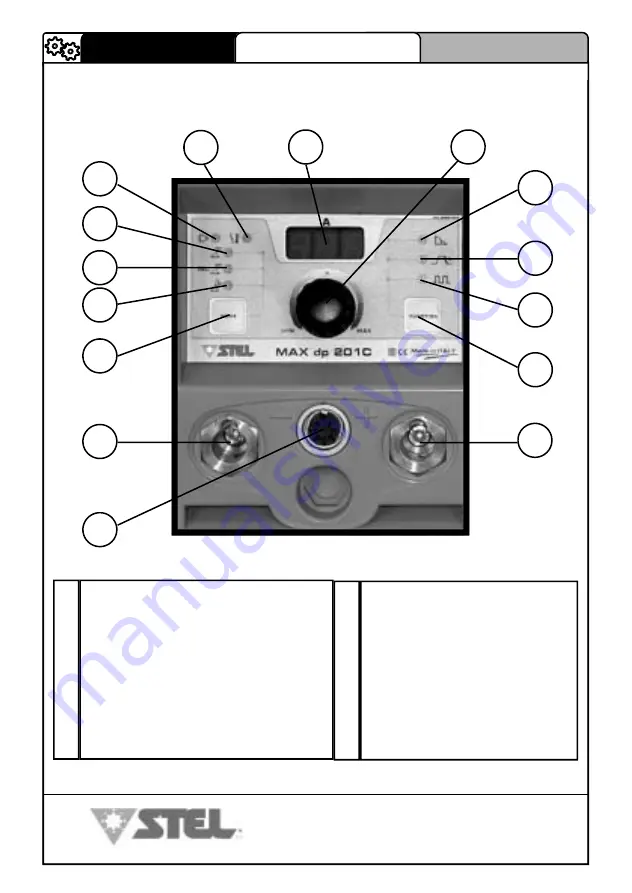
5.1- COMANDI PANNELLO FRONTALE 

DESCRIZIONE TECNICA 

ITALIANO 

2


3


4


5


6


7


8


9


10


11


12


13


14


15


Connettore comando remoto 
Presa attacco polarità negativa 
Pulsante selezione modalità saldatura / vrd 
Led segnalazione modalità saldatura TIG 
Led segnalazione modalità saldatura elettrodo cellulosico 
Led segnalazione modalità saldatura elettrodo  
Led segnalazione macchina sotto tensione 
Led segnalazione intervento sovratemperatura 
Display visualizzazione corrente saldatura/vari parametri 
Encoder di regolazione 


10 

Led segnalazione funzione ARC-FORCE 
Led segnalazione funzione rampa di discesa 
Led segnalazione funzione pulsazione  
Pulsante selezione funzioni 
Presa attacco polarità positiva 

11 
12 
13 
14 
15 

141 

MAX dp 171-201C  

COD. 6910700020 

STEL s.r.l. – Via del Progresso n° 59 – 36020 

Loc. Castegnero (VICENZA) - ITALY 

TEL. +39 444 639525 (central.) – +39 444 639682 (comm.) 

FAX +39 444 639641 – E-mail: stel @ stelgroup.it 

http: www.stelgroup.it 

ENGLISH 

13.0- EXPLODED VIEWS AND LIST OF COMPONENTS  

13.1– EXPLODED VIEW MAX dp 171/201C 

SPARE PARTS 

10 

11 

12 

13 

14  15 

16 

17 

18 

19 

20 

21 

22 

24 

25 

26 

23 

Summary of Contents for MAX dp 171C

Page 1: ...RA EL USO Y EL MANTENIMIENTO PRIMADI UTILIZZARE LAMACCHINAE OBBLIGATORIOLEGGEREE COMPRENDEREIN TUTTE LE SUEPARTI IL SEGUENTEMANUALE YOUHAVETOREADCAREFULLYALLTHIS MANUALBEFOREUSINGWELDINGMACHINE AVANT D UTILISERLEGENERATEUR ILFAUT LIREETCOMPRENDRE TOUTES LESSECTIONS DU MANUEL BEVORDIEMASCHINEINGEBRAUCHGENOMMENWIRD MUSS DIEBEDIENUNGSPERSONOBLIGATORISCHDIESES HANDBUCHINALLSEINENTEILENGELESEN UNDVERST...

Page 2: ...armonisierten Normen angewandt wurden asimismo declara que se han aplicado las siguientes normas armonizadas QUALSIASI MODIFICA ALLA MACCHINA SENZA L AUTORIZZAZIONE DI STEL s r l RENDERÀ NULLA QUESTA DICHIARAZIONE ANY MODIFICATION OF THE MACHINE WITHOUT THE AUTHORISATION OF STEL s r l RENDERS THIS DECLARATION VOID TOUTE MODIFICATION APPORTÉE À LA MACHINE SANS L AUTORISATION DE STEL s r l ANNULERA ...

Page 3: ...elgroup it Gentile Cliente grazie per la fiducia accordataci Le macchine MAX dp 171 201C sono costruite secondo la filosofia STEL che associa qualità ed affidabilità nella conformità delle normative sulla sicurezza Grazie alla tecnologia con cui sono costruite MAX dp 171 201C risulta no avere delle caratteristiche dinamiche ottimizzate per delle massime prestazioni di saldatura PRESENTAZIONE ITALI...

Page 4: ...DATURA TIG 7 1 PROCEDIMENTI DELLA SALDATURA TIG 7 2 FASI DELLA SALDATURA TIG 8 0 DESCRIZIONE FUNZIONI DI SALDATURA 8 1 SALDATURA AD ELETTRODO 8 2 SALDATURA AD ELETTRODO CELLULOSICO CEL 8 3 SALDATURA TIG 9 0 PREDISPOSIZIONE COMANDO A DISTANZA TORCIA UP DOWN 10 0 V R D 10 1 GESTIONE V R D 10 2 ATTIVAZIONE DEL V R D 10 3 ESCLUSIONE DEL V R D 11 0 FIGURE 11 1 DISTANZA POSTERIORE LATERALI DA MANTENERE ...

Page 5: ...enitori sotto pressione non saldare in ambienti contenenti polveri o vapori esplosivi LE RADIAZIONI GENERATE DALL ARCO Dl SALDATURA POSSONO DANNEG GIARE GLI OCCHI E PROVOCARE BRUCIATURE ALLA PELLE Proteggere gli occhi ed il corpo adeguatamente È indispensabile per i portatori di lenti a contatto proteggersi con apposite lenti e maschere IL RUMORE PUÒ DANNEGGIARE L UDITO Proteggersi adeguatamente p...

Page 6: ...entrazioni elevate di polveri gas infiammabili o vapori combustibili PREVENZIONE CONTRO SHOCK ELETTRICI Prendere le seguenti precauzioni quando si opera con un generatore di corrente tenere puliti se stessi ed i propri vestiti non essere a contatto con parti umide e bagnate quando si opera con il generatore mantenere un isolamento adeguato contro gli shock elettrici Se l operatore deve lavora re i...

Page 7: ...limentazione Fasi Frequenza Corrente nominale ED 20 Corrente nominale ED 100 Potenza nominale ED 20 Potenza nominale ED 100 Tensione a vuoto Tensione d arco Fattore di potenza ED 20 Fusibili di protezione Cavo di alimentazione Campo di regolazione corrente Corrente saldatura ED 20 Corrente saldatura ED 100 Cavi di saldatura Grado di protezione Classe di isolamento Raffreddamento Temperatura massim...

Page 8: ...llo cod 6700200000 N 1 cinghia cod 6604480000 2 composizione GEN MAX dp 201C VALIGETTA COD VENDITA 607850000L N 1 generatore cod 607820000L N 1 libretto istruzioni cod 6910700020 N 1 certificato di garanzia cod 6627800000 N 1 imballo cod 6700200000 N 1 valigia cod 608850000L N 1 kit cavi da 25mm cod 602060000L N 1 cinghia cod 6604480000 3 2 RECLAMI Reclami per danneggiamento durante il trasporto S...

Page 9: ...to impiegare questa macchina con gruppi elettrogeni che non rispettino queste condi zioni perché si può danneggiare COLLEGAMENTO Prima di effettuare connessioni elettriche tra il generatore di corrente e l interruttore di linea accer tarsi che quest ultimo sia aperto Il quadro di distribuzione deve essere conforme alle normative vigenti nel paese di utilizzo L impianto di rete deve essere di tipo ...

Page 10: ...tà negativa Pulsante selezione modalità saldatura vrd Led segnalazione modalità saldatura TIG Led segnalazione modalità saldatura elettrodo cellulosico Led segnalazione modalità saldatura elettrodo Led segnalazione macchina sotto tensione Led segnalazione intervento sovratemperatura Display visualizzazione corrente saldatura vari parametri Encoder di regolazione 1 2 3 4 5 6 7 8 9 10 Led segnalazio...

Page 11: ...lo del processo di saldatura Simbolo per le saldatrici idonee ad operare in ambiente a rischio accresciuto di scossa elettrica Simbolo della corrente di saldatura Tensione assegnata a vuoto tensione media Gamma della corrente di saldatura Valori del ciclo di intermittenza su 10 minuti Valori della corrente assegnata di saldatura Valori della tensione convenzionale a carico c ALIMENTAZIONE Simbolo ...

Page 12: ...di selezione RIF N 3 pag 8 fino a far accendere il led di indicazione modalità Elettrodo RIF N 6 pag 8 5 Inserire l anima scoperta dell elettrodo nella pinza 6 Per le impostazioni fare riferimento al capitolo 8 1 5 4 DISPOSIZIONE SALDATURA TIG FIG 7 1 Rispettare le indicazioni fornite precedentemente a riguardo dell allacciamento primario e dell installazione 2 Collegare il cavo di massa alla pres...

Page 13: ...inox ed ha la funzione di ap portare materiale nel giunto b il rivestimento costituito da varie sostanze minerali ed orga niche miscelate fra loro le cui funzioni sono Protezione gassosa Una parte del rivestimento volatizzata alla temperatura dell arco allontana l aria dalla zona di saldatura creando una colonna di gas ionizzato che protegge il metallo fuso Apporto di elementi leganti e scorifican...

Page 14: ...i varia a seconda dello spessore del materiale da salda re della posizione di saldatura dal tipo di giunto e dalle esigenze di realizzazione Comunque è sempre consigliabile lavorare su parti pulite non ossidate o che non presentino ruggine o altre sostanze che potrebbero danneggiare la saldatura I lembi possono venire preparati con delle cianfrinature ad U per una saldatura senza ripresa ad X quan...

Page 15: ... elettrodo fino al mantenimento dell arco Un movimento troppo lento può provocare l incoraggio dell elettrodo al pezzo in questo caso con uno strappo laterale si libera l elettrodo mentre un movimento troppo veloce può provocare lo spegnimento dell arco Esecuzione della saldatura Le tecniche per eseguire l unione dei giunti sono molteplici e variano a seconda delle esigenze dell operatore Prendere...

Page 16: ...o vimento dell elettrodo viene eseguito tramite oscillazioni e fermate ai lati del cordo ne in modo da evitare l accumulo di materiale d apporto al centro della saldatura Asportazione della scoria Per gli elettrodi rivestiti si rende necessaria l asportazione della scoria dopo ogni passata L asportazione si esegue tramite un piccolo martello oppure per scorie friabili con una spazzola metallica Pe...

Page 17: ...iti condotti collegati alla torcia Per semplicità e uniformità ogni riferimento al processo in questo manuale viene fatto con il termine TIG Tungsten Inert Gas Questo processo può essere usato per fare saldature pulite e precise su ogni tipo di metallo rispettandone la composizione fisico chimica Grazie a questa caratteristica la saldatura TIG rappresenta il solo metodo adatto per unire certi meta...

Page 18: ...ra la tabella seguente ne consi glia il valore c Materiale d apporto Esistono molti materiali trattabili comunque valgono alcune regole basilari 1 le bacchette di materiale d apporto devono rispettare le stesse proprietà meccaniche e chimiche del materiale da saldare 2 è sconsigliato utilizzare parti del materiale base in quanto potreb bero contenere impurità dovute alla lavorazione stessa 3 se il...

Page 19: ...ogni saldatura effettuare un accurata preparazione e pulizia dei lembi SALDATURA TIG DEL RAME Per le proprietà già descritte la saldatura TIG risulta ottimale anche nel caso della lavorazione di materiali ad elevata conducibilità termica Il gas utilizzato è sempre l argon e nel caso della saldatura del rame si consiglia l uso di un supporto rovescio Preparazione dei lembi per la saldatura del rame...

Page 20: ...e rif 11 pag 8 è acceso 5 Regolazione corrente di saldatura Con l encoder rif 10 pag 8 si regola la corrente di saldatura visualizzata sul display rif 9 pag 8 6 l Hot Start è già regolato automaticamente per avere una saldatura ottimale 7 Regolazione Arc Force Premendo il pulsante Function rif 14 pag 8 si sele ziona il valore di Arc Force Il display rif 9pag 8 comincerà a lampeggiare mo strando pr...

Page 21: ...o il pulsante Function rif 14 pag 8 si sele ziona il valore di Arc Force Il display rif 9 pag 8 comincerà a lampeggiare mo strando prima la scritta A F e indicando poi il valore selezionabile con l encoder rif 10 pag 8 L Arc Force può essere variato da 0 al 500 rispetto al valore di corrente di saldatura impostato 8 Attivazione e regolazione Frequenza di pulsazione in CEL mode Premen do una succes...

Page 22: ...pa di discesa può essere esclusa portando al minimo la regolazione dell encoder compare la scritta OFF sui display La regolazione della rampa varia da 0 1s a 10secondi 7 Attivazione e regolazione Frequenza di pulsazione in tiG mode Premen do una successiva volta il pulsante Function rif 14 pag 8 si attiva la modalità pulsazione Il led pulsazione rif 13 pag 8 comincerà a lampeggiare ed il display m...

Page 23: ... 1 In modalità TIG si può terminare la saldatura con la funzione rampa di discesa slope down agendo sulla distanza dell arco dal pezzo di saldatura 2 Portando in posizione OFF la rampa di discesa l operatore dovrà strappare l ar co per terminare la saldatura In figura n 1 vediamo che per terminare la saldatura si può alzare la torcia dal pezzo dando così inizio alla rampa di discesa ITALIANO DESCR...

Page 24: ...nettore automa ticamente la macchina si predispone per la regolazione con comando remoto Il punto di destra del display rif 9 pag 8 lampeggia La corrente di saldatura varia dal mini mo 4A ad un massimo impostabile sulla macchina tramite l encoder di regolazione rif 10 pag 8 Per disattivare la funzione comando remoto occorre staccare il connettore del co mando a distanza FUNZIONAMENTO DELLA TORCIA ...

Page 25: ... sul lavoro devono sempre essere seguite con atten zione 10 2 ATTIVAZIONE DEL V R D 1 Accendere il generatore 2 Tener premuto il pulsante MODE rif 3 pag 8 sul panello frontale della macchina per circa 5 secondi rilasciare poi il pulsante il led di modalità lampeggia FUNZIONE V R D INSERITA Vout 25V La modalità VRD rimane sempre inserita in tutti i tipi di saldatura anche dopo lo spegnimento e la r...

Page 26: ...elgroup it http www stelgroup it MAX dp 171 201C COD 6910700020 11 0 FIGURE 11 1 DISTANZE POSTERIORI E LATERALI DA MANTENERE DU RANTE LA SALDATURA 11 2 SEGNALETICA DI SICUREZZA SEGNALETICA DI SICUREZZA PER SALDATRICI CONFORME ALLA DIRETTIVA 92 58 CEE E ALLE NORME UNI 7543 1 3 ATTENZIONE ATTENTION BEWARE ACHTUNG ATENCION ITALIANO DESCRIZIONE TECNICA ...

Page 27: ...ttenza è la percentuale su 10 minuti che l operatore deve rispettare per non entrare in sovratemperatura Se la macchina entra in sovratemperatura il led giallo rif 3 pag 8 si accende E necessario quindi attendere circa 10 minuti per riprendere a saldare Occorre ridurre l amperaggio o il tempo di lavoro dopo aver ripreso a saldare ITALIANO FIGURE 10 minuti Saldatura continua 100 ED ciclo intermitte...

Page 28: ...O Curva statica MAX dp 171C Curva statica MAX dp 201C 11 4 CURVE TENSIONE CORRENTE VOLTS AMPER FIGURE St at ic charact erist ic M ax dp 171C 1F 0 10 20 30 40 50 60 70 80 0 20 40 60 80 100 120 140 160 180 Cur r ent A M AX dp 171C Ioutmax160A M AX dp 171C Ioutmi n4A St at ic charact erist ic M ax dp 2 0 1C 1F 0 20 40 60 80 100 120 0 25 50 75 100 125 150 175 200 Cur r ent A M AX dp 201C Ioutmax200A M...

Page 29: ...ATI Inclinazione elettrodo eccessiva Effettuare le opportune correzioni DIFETTI Dl PROFILI Parametri saldatura non corretti Velocità passata non legata alle esigenze dei parametri operativi Inclinazione dell elettrodo non costante durante la saldatura Rispettare i principi basilari e generali di saldatura INSTABILITÀ D ARCO Corrente insufficiente Controllare lo stato dell elettrodo e il colle game...

Page 30: ...lizia interna che va eseguita tanto più spesso quanto più polveroso è l ambiente di lavoro Togliere la copertura Togliere ogni traccia di polvere dalle parti interne del generatore mediante getto d aria compressa con pressione non superiore a 3 Kg cm2 Controllare tutte le connessioni elettriche assicurandosi che viti e dadi siano ben serrati Non esitare nel sostituire i componenti deteriorati Rimo...

Page 31: ...up it http www stelgroup it Dear Customer Thank you for choosing our product MAX dp 171 201C machines are built according to STEL philosophy which combines quality and reliability with the respect of safety regulations Thanks to the technology with which they are built the MAX dp 171 201C have optimum dynamic characteristics to ensure maximum welding performances PRESENTATION ENGLISH ...

Page 32: ...URES 6 2 ELECTRODE WELDING PHASES 7 0 TIG WELDING 7 1 TIG WELDING PROCEDURES 7 2 TIG WELDING PHASES 8 0 DESCRIPTION OF THE WELDING FUNCTIONS 8 1 ELECTRODE WELDING 8 2 CELLULOSE ELECTRODE WELDING CEL 8 3 TIG WELDING 9 0 PREPARING THE REMOTE CONTROL TORCH UP DOWN 10 0 V R D 10 1 V R D MANAGEMENT 10 2 ACTIVATING THE V R D 10 3 EXCLUDING THE V R D 11 0 FIGURES 11 1 REAR AND SIDE DISTANCES TO BE KEPT D...

Page 33: ...rent generator do not weld pressurized containers do not weld in environments containing explosive powders or vapours THE RADIATIONS GENERATED BY THE WELDING ARC CAN DAMAGE THE EYES AND CAUSE BURNING OF THE SKIN Provide suitable protection for the eyes and body It is indispensable for contact lens wearers to protect themselves with suitable lenses and masks NOISE CAN DAMAGE YOUR HEARING Protect yo...

Page 34: ...chine in atmospheres containing high concentrations of pow ders inflammable gases or combustible vapours PREVENTION OF ELECTRIC SHOCK Take the following precautions when working with a current generator keep yourself and your clothes clean do not be in contact with damp or wet parts when working with the generator maintain suitable insulation against electric shock If the operator has to work in a...

Page 35: ...ECHNICAL DESCRIPTION Supply voltage Phases Frequency Rated current ED 20 Rated current ED 100 Rated power ED 20 Rated power ED 100 No load voltage Arc voltage Power factor ED 20 Protective fuses Power cable Current regulating range Welding current ED 20 Welding current ED 100 Welding cables Degree of protection Insulating class Cooling Maximum work temperature Arc force ARC Arc force CUR Pulsating...

Page 36: ...10700020 N 1 guarantee certificate code 6627800010 N 1 packaging code 6700200000 N 1 strap code 6604480000 2 composition GEN MAX dp 201C CASE SALES CODE 607850000L N 1 generator code 607820000L N 1 instructions manual code 6910700020 N 1 guarantee certificate code 6627800000 N 1 packaging code 6700200000 N 1 case code 608850000L N 1 kit cables 25mm code 602060000L N 1 strap code 6604480000 3 2 COM...

Page 37: ...n points 1 and 2 It is advised not to use this machine with generating sets that do not fulfil these conditions because it might be damaged CONNECTION Before making any electrical connections between the current generator and the line switch make sure that the switch is turned off The distribution panel must comply with the regulations in force in the country of use The mains system must be of the...

Page 38: ...ontrol connector Negative polarity coupling socket Weld vrd mode selection button TIG weld mode indicating led Cellulose electrode weld mode indicating led Electrode weld mode indicating led Machine live indicating led Excess temperature intervention indicating led Display showing weld current various parameters Regulating encoder 1 2 3 4 5 6 7 8 9 10 ARC FORCE function indicating led Slope Down f...

Page 39: ...rds b WELDING OUTPUT Symbol of the welding process Symbol for welding machines suitable for working in an environment with a high risk of electric shock Symbol of the welding current Assigned no load voltage mean voltage Range of the welding current Values of the intermittence cycle in 10 minutes Values of the assigned welding current Values of the conventional loaded voltage c POWER SUPPLY Power ...

Page 40: ... REF N 15 pag 8 4 Press the selection button REF N 3 pag 8 to switch on the Electrode mode indicating led REF N 6 pag 8 5 Insert the bare core of the electrode in the gun 6 For the settings refer to chapter 8 1 5 4 PREPARING FOR TIG WELDING FIG 7 1 Respect the indications given previously concerning primary connection and installation 2 Connect the earth cable to the positive socket of the machine...

Page 41: ...osed of various mineral and organic substances mixed together its functions are Gas protection A part of the coating volatised at arc temperature sends air away from the welding zone creating a column of ionised gas which protects the molten metal Supply of bonding and scarifying elements A part of the coating melts and supplies elements to the weld pool which combine with the base material formin...

Page 42: ... it is always advisable to work on clean parts free from oxide or without rust or other substances that could damage the weld The edges can be prepared with U section calking for a weld without rewelding with X section calking when rewelding of the reverse weld is needed Table for preparing U shaped edges b Choosing the electrode The choice of the electrode diameter depends on the thickness of the...

Page 43: ...arc is maintained If the movement is too slow it may cause the electrode to stick to the part in this case the electrode may be freed by pulling it to one side on the other hand if the movement is too fast it may extinguish the arc Making the weld There are many techniques for making the joints and they vary according to the operator s requirements Two classical methods will be studied as an examp...

Page 44: ...es according to the passes made the movement of the electrode is performed by swinging it and stopping at the sides of the seam so as to avoid the accumulation of weld material in the centre of the weld Removing slag For coated electrodes it is necessary to remove the slag after each pass The slag is removed with a small hammer or in the case of brittle slag with a wire brush To make the different...

Page 45: ...as such as argon or helium which flows continu ously through special ducts connected to the torch For the sake of simplicity and uniformity all references to the process in this manual are made with the term TIG Tungsten Inert Gas This process may be used for making clean and precise welds on any type of metal respecting its physical and chemical composition Thanks to this characteristic TIG weldi...

Page 46: ... value c Weld material Many kinds of materials may be treated however there are some basic rules 1 the rods of weld material must have the same mechanical and chemical proper ties as the material to be welded 2 it is recommended not to use parts of the base material as they could contain im purities due to the work process 3 if the material used has a different chemical composition it is advisable...

Page 47: ...es TIG WELDING ON COPPER Due to the properties already described TIG welding is also excellent for working on materials with high heat conductivity The gas used is always argon and in the case of copper the use of a reversed support is recommended Preparation of the edges for welding copper flat butt joint The electrode used is of the same type described for welding steel it is prepared as describ...

Page 48: ...lding current The encoder ref 10 page 8 is used to regulate the welding current shown on the display ref 9 page 8 6 The Hot Start value is already automatically regulated to have an optimum weld 7 Regulating the Arc Force Pressing the Function button ref 14 page 8 selects the Arc Force value The display ref 9 page 8 will start to blink indicating first the let ters A F and then the value that can ...

Page 49: ...he Arc Force Pressing the Function button ref 14 page 8 selects the Arc Force value The display ref 9 page 8 will start to blink indicating first the let ters A F and then the value that can be selected with the encoder ref 10 page 8 The Arc Force may be varied from 0 to 500 with respect to the set welding current value 8 Activating and regulating the Pulse Frequency in CEL mode Pressing the Funct...

Page 50: ...age 8 The slope down may be excluded by reducing the encoder regulation to a minimum the letters OFF appear on the display The slope regulation varies from 0 1s to 10 sec onds 7 Activating and regulating the Pulse Frequency in tiG mode Pressing the Function button again ref 14 page 8 activates pulse mode The pulse led ref 13 page 8 will start to blink and the display will show the letters P Fr By ...

Page 51: ...elgroup it End of welding WELDING CURRENT FIG N 1 1 In TIG mode you can end welding with the slope down function by regulating the distance of the arc from the piece being welded 2 Turning the slope down to OFF position the operator must pull away the arc to end welding Figure n 1 shows how to end welding the torch can be lifted from the piece thus starting the slope down ENGLISH TECHNICAL DESCRIP...

Page 52: ... is inserted in the connector provided the machine auto matically prepares for remote control regulation The dot on the right of the display ref 9 page 8 blinks The welding current varies from the minimum 4A to a maxi mum which may be set on the machine by means of the regulating encoder ref 10 page 8 To deactivate the remote control function disconnect the remote control connector TORCH UP DOWN O...

Page 53: ...e procedures for safety at work must always be scrupulously followed 10 2 ACTIVATING THE V R D 1 Switch on the generator 2 Hold down the MODE button ref 3 page 8 on the front panel of the machine for about 5 seconds then release the button the mode led blinks V R D FUNCTION ON Vout 25V VRD mode remains always activated in all types of welding even after switching the machine off and on again 10 3 ...

Page 54: ...up it MAX dp 171 201C COD 6910700020 11 0 FIGURES 11 1 REAR AND SIDE DISTANCES TO BE MAINTAINED DURING WELDING 11 2 SAFETY SIGNS SAFETY SIGNS FOR WELDING MACHINES IN COMPLIANCE WITH DIRECTIVE 92 58 EEC AND WITH STANDARDS UNI 7543 1 3 ENGLISH TECHNICAL DESCRIP 11 0 FIGURES 11 1 REAR AND SIDE DISTANCES TO BE MAINTAINED DURING WELDING ATTENZIONE ATTENTION BEWARE ACHTUNG ATENCION ...

Page 55: ...cle is the percentage of use in 10 minutes which the operator must respect so as to avoid excess temperature If the machine goes into excess temperature the yellow led ref 3 page 8 lights up It is therefore necessary to wait about 10 minutes before resuming welding The current or the work time must be reduced after resuming welding ENGLISH FIGURES 10 minutes Continuous weld 100 ED intermittence cy...

Page 56: ...dp 171C Static curve MAX dp 201C 11 4 VOLTAGE CORRENT CURVES VOLTS AMPERES FIGURES St at i c char act er i st i c M ax dp 171C 1F 0 10 2 0 3 0 4 0 5 0 6 0 7 0 8 0 0 2 0 4 0 6 0 8 0 10 0 12 0 14 0 16 0 18 0 C u r r e n t A M AX dp 17 1C I out max16 0 A M AX dp 17 1C I out mi n 4 A St at ic charact erist ic M ax d p 2 0 1C 1F 0 20 40 60 80 100 120 0 25 50 75 100 125 150 175 200 Cur r ent A M AX dp 2...

Page 57: ... its movement Regulate the operative parameters and improve preparation of the parts to be welded HIGH SPLASHING Excessive electrode inclination Make the necessary corrections PROFILE DEFECTS Incorrect welding parameters Passing speed not linked with the needs of the operative parameters Electrode inclination not constant during welding Respect the basic and general welding principles ARC INSTABIL...

Page 58: ... the dustier the working environment the more frequently the inside should be cleaned Remove the cover Remove every trace of dust from the internal parts of the generator using a jet of compressed air with pressure not higher than 3 Kg cm2 Check all the electrical connections ensuring that screws and nuts are firmly se cured Do not hesitate to replace worn components Replace the cover Once the abo...

Page 59: ... Cher Client Merci pour votre confiance Les machines MAX dp 171 201C sont construites selon la philosophie STEL qui garantit non seulement la qualité et la fiabilité de ses produits mais aussi la conformité aux normes de sécurité Grâce à leur technologie de construction les MAX dp 171 201C ont des caractéristiques dynamiques optimisées pour des performances de sou dage de très haut niveau PRÉSENTA...

Page 60: ...CTRODE 6 2 PHASES DU SOUDAGE À L ÉLECTRODE 7 0 SOUDAGE TIG 7 1 PROCÉDÉS DU SOUDAGE TIG 7 2 PHASES DU SOUDAGE TIG 8 0 DESCRIPTION DES FONCTIONS DE SOUDAGE 8 1 SOUDAGE À L ÉLECTRODE 8 2 SOUDAGE À L ÉLECTRODE CELLULOSIQUE CEL 8 3 SOUDAGE TIG 9 0 PRÉÉQUIPEMENT COMMANDE À DISTANCE TORCHE UP DOWN 10 0 V R D 10 1 GESTION V R D 10 2 ACTIVATION DU V R D 10 3 EXCLUSION DU V R D 11 0 FIGURES 11 1 DISTANCES A...

Page 61: ... pression ne pas souder dans des lieux où sont présentes des poussières et des vapeurs explo sives LES RADIATIONS GÉNÉRÉES PAR L ARC DE SOUDAGE PEUVENT LÉSER LES YEUX ET CAUSER DES BRÛLURES CUTANÉES Protéger adéquatement les yeux et le corps pour les personnes qui portent des lentilles de contact il est indispensable de se protéger avec des lunettes et des masques spéciaux LE BRUIT PEUT LÉSER L OU...

Page 62: ...ne dans des atmosphères qui contiennent des concentrations éle vées de poussières des gaz inflammables ou des vapeurs combustibles PRÉVENTION CONTRE LES CHOCS ÉLECTRIQUES Prendre les précautions suivantes quand on travaille avec un générateur de courant être toujours propre ainsi que ses vêtements ne pas être en contact avec des parties humides et mouillées quand on travaille avec le générateur ma...

Page 63: ...ON TECHNIQUE V Hz A A KVA KVA V V PF A mm mm A A mm IP C Hz sec mm mm mm Kg MAX dp 171C 230 1 50 60 34 20 7 5 4 6 72 20 16 26 4 0 7 16 2 5 x 3 4 160 160 110 25 23 H AF 40 0 200 0 500 0 4 5 330 135 280 6 5 230 1 50 60 23 14 3 5 3 3 3 72 10 16 26 4 0 7 16 2 5 x 3 4 160 160 110 25 23 H AF 40 0 4 999 0 1 10 330 135 280 6 5 MAX dp 201C 230 1 50 60 43 29 9 6 100 20 16 28 0 7 20 4 x 3 4 200 200 140 35 23...

Page 64: ...on GEN MAX dp 201C CODE VENTE 607830000L 1 générateur code 607820000L 1 notice technique code 6910700020 1 certificat de garantie code 6627800010 1 emballage code 6700200000 1 courroie code 6604480000 2 composition GEN MAX dp 201C MALLETTE CODE VENTE 607850000L 1 générateur code 607820000L 1 notice technique code 6910700020 1 certificat de garantie code 6627800000 1 emballage code 6700200000 1 mal...

Page 65: ...RMS de l onde en c a supérieure à 180 V c a Il est important que le groupe électrogène satisfasse les conditions indiquées aux points 1 et 2 Il est déconseillé d employer cette machine avec des groupes électrogènes qui ne respectent pas ces conditions car cela pourrait l endommager BRANCHEMENT Avant d effectuer les connexions électriques entre le générateur de courant et l interrupteur de li gne s...

Page 66: ... polarité négative Bouton de sélection mode de soudage VRD DEL de signalisation mode de soudage TIG DEL de signalisation mode de soudage électrodecellulosique DEL de signalisation mode de soudage électrode DEL de machine sous tension DEL de signalisation intervention échauffement Afficheur courant de soudage paramètres divers Encodeur de réglage 1 2 3 4 5 6 7 8 9 10 DEL de signalisation fonction A...

Page 67: ...es pouvant fonctionner dans des atmosphères à risque accru de choc électrique Symbole du courant de soudage Tension assignée à vide tension moyenne Gamme du courant de soudage Valeurs du cycle d intermittence sur 10 minutes Valeurs du courant de soudage assigné Valeurs de la tension conventionnelle à charge c ALIMENTATION Symbole pour l alimentation nombre de phases et fréquence Tension d alimenta...

Page 68: ... sélection réf n 3 page 8 de manière à provoquer l al lumage de la DEL d indication mode Électrode réf n 6 page 8 5 Insérer l âme mise à nue dans l électrode de la pince 6 Pour les réglages se référer au chapitre 8 1 5 4 DISPOSITION SOUDAGE TIG FIG 7 1 Respecter les indications fournies plus haut en ce qui concerne le raccordement primaire et de l installation 2 Connecter le câble de masse à la pr...

Page 69: ...cuivre acier inox et a la fonction d apporter le matériau dans le joint b l enrobage constitué de différentes substances minérales et organiques mélangées qui ont les fonctions suivantes Protection gazeuse Une partie de l enrobage volatilisée à la température de l arc éloigne l air de la zone de soudage en créant une colonne de gaz ionisé qui protège le métal fondu Apport d éléments d alliage et d...

Page 70: ...s à souder La préparation des bords varie suivant l épaisseur du matériau à souder la position de la soudure le type de joint et les exigences de réalisation Il est toujours conseillé dans tous les cas d opérer sur des pièces propres non oxydées ou qui ne présen tent pas de rouille ou autres substances qui pourraient endommager la soudure Les bords peuvent être chanfreinés en U pour une soudure sa...

Page 71: ...pièce à souder et en éloignant rapidement l électrode pour établir l arc électrique Un mouvement trop lent peut provoquer le collage de l électrode à la pièce dans ce cas on libère l électrode en tirant sur le côté tandis qu un mouvement trop ra pide peut provoquer l extinction de l arc Exécution de la soudure Les techniques pour effectuer l union des joints sont multiples et varient suivant les e...

Page 72: ...ées le mouve ment de l électrode est effectué par oscillations et arrêts sur les côtés du cordon de manière à éviter l accumulation de matériau d apport au centre de la soudure Élimination des scories de laitier Pour les électrodes enrobées il est nécessaire d éliminer les scories de laitier après chaque passe L élimination s effectue avec un petit marteau ou bien avec une bros se métallique pour ...

Page 73: ...ciaux reliés à la torche Pour plus de simplicité et uniformité toute référence au procédé dans cette notice uti lise le terme TIG Tungsten Inert Gas Ce procédé peut être utilisé pour faire des soudures propres et précises sur tous les types de métaux en en respectant la composition physico chimique Grâce à cette caractéristique le soudage TIG représente l unique méthode possible pour assembler cer...

Page 74: ... traitables auxquels s appliquent dans tous les cas quelques règles de base 1 les baguettes de matériau d apport doivent respecter les mêmes propriétés mécaniques et chimiques que le métal à souder 2 il est déconseillé d utiliser des parties du matériau de base dans la mesure où elles pourraient contenir des impuretés dues au soudage proprement dit 3 si le matériau utilisé a une composition chimiq...

Page 75: ...fait des propriétés décrites plus haut le soudage TIG se révèle particulièrement adapté pour les métaux à haute conductibilité thermique Le gaz utilisé est toujours l argon et dans le cas du soudage du cuivre il est conseillé d utiliser un support en vers Préparation des bords pour le soudage du cuivre joint bout à bout à plat L électrode utilisée est du même type que celle décrite pour le soudage...

Page 76: ...Arc Force réf 11 page 8 est allumée 5 Réglage courant de soudage Avec l encodeur réf 10 page 8 on règle le cou rant de soudage visible sur l afficheur réf 9 page 8 6 Le Hot Start est déjà réglé automatiquement pour avoir une soudure optimale 7 Réglage Arc Force En appuyant sur le bouton Function réf 14 page 8 on sé lectionne la valeur d Arc Force L afficheur réf 9 page 8 commencera à clignoter en ...

Page 77: ...Arc Force réf 11 page 8 est allumée 5 Réglage courant de soudage Avec l encodeur réf 10 page 8 on règle le cou rant de soudage visible sur l afficheur réf 9 page 8 6 Le Hot Start est déjà réglé automatiquement pour avoir une soudure optimale 7 Réglage Arc Force En appuyant sur le bouton Function réf 14 page 8 on sé lectionne la valeur d Arc Force L afficheur réf 9 page 8 commencera à clignoter en ...

Page 78: ... En appuyant sur le bouton Function réf 14 page 8 on sé lectionne la valeur d Arc Force L afficheur réf 9 page 8 commencera à clignoter en affichant d abord A F et en indiquant ensuite la valeur sélectionnable avec l encodeur réf 10 page 8 L Arc Force peut être varié de 0 à 500 par rapport à la valeur de courant de soudage sélectionnée 8 Activation et réglage Fréquence de pulsation en CEL mode En ...

Page 79: ... traitables auxquels s appliquent dans tous les cas quelques règles de base 1 les baguettes de matériau d apport doivent respecter les mêmes propriétés mécaniques et chimiques que le métal à souder 2 il est déconseillé d utiliser des parties du matériau de base dans la mesure où elles pourraient contenir des impuretés dues au soudage proprement dit 3 si le matériau utilisé a une composition chimiq...

Page 80: ...e FIG N 1 1 En mode TIG on peut terminer le soudage avec la fonction rampe de descente slope down en agissant sur la distance de l arc par rapport à la pièce soudée 2 En mettant la rampe de descente dans la position OFF l opérateur devra arracher l arc pour mettre fin au soudage Dans la figure n 1 nous voyons que pour mettre fin au soudage on peut soulever la torche de la pièce en faisant commence...

Page 81: ...ées le mouve ment de l électrode est effectué par oscillations et arrêts sur les côtés du cordon de manière à éviter l accumulation de matériau d apport au centre de la soudure Élimination des scories de laitier Pour les électrodes enrobées il est nécessaire d éliminer les scories de laitier après chaque passe L élimination s effectue avec un petit marteau ou bien avec une bros se métallique pour ...

Page 82: ...la sécurité au travail doivent toujours être suivies avec atten tion 10 2 ACTIVATION DU V R D 1 Allumer le générateur 2 Maintenir la pression sur le bouton MODE réf 3 page 8 sur le panneau de façade de la machine pendant environ 5 secondes relâcher ensuite le bouton la DEL Mode clignote FONCTION V R D ACTIVÉE Vout 25 V Le mode VRD reste toujours activé dans tous les types de soudage même après avo...

Page 83: ...s à souder La préparation des bords varie suivant l épaisseur du matériau à souder la position de la soudure le type de joint et les exigences de réalisation Il est toujours conseillé dans tous les cas d opérer sur des pièces propres non oxydées ou qui ne présen tent pas de rouille ou autres substances qui pourraient endommager la soudure Les bords peuvent être chanfreinés en U pour une soudure sa...

Page 84: ...e est le pourcentage sur 10 minutes que l opérateur doit res pecter pour ne pas risquer l échauffement Si la machine s échauffe la DEL jaune réf 3 page 8 s allume Il faut donc attendre environ 10 minutes avant de recommencer à souder Il faut réduire l ampérage ou le temps de travail après avoir recommencé à souder FRANÇAIS FIGURES 10 minutes Soudage continu 100 ED cycle d intermittence 3 5 minutes...

Page 85: ... sélection réf n 3 page 8 de manière à provoquer l al lumage de la DEL d indication mode Électrode réf n 6 page 8 5 Insérer l âme mise à nue dans l électrode de la pince 6 Pour les réglages se référer au chapitre 8 1 5 4 DISPOSITION SOUDAGE TIG FIG 7 1 Respecter les indications fournies plus haut en ce qui concerne le raccordement primaire et de l installation 2 Connecter le câble de masse à la pr...

Page 86: ...RTANTES Inclinaison de l électrode excessive Effectuer les corrections nécessaires DÉFAUTS DE PROFILS Paramètres de soudage incorrects Vitesse de passage non liée aux exigences des paramètres de travail Inclinaison de l électrode non constante durant le soudage Respecter les principes de base et généraux de soudage INSTABILITÉ DE L ARC Courant insuffisant Contrôler l état de l électrode et le bran...

Page 87: ... polarité négative Bouton de sélection mode de soudage VRD DEL de signalisation mode de soudage TIG DEL de signalisation mode de soudage électrodecellulosique DEL de signalisation mode de soudage électrode DEL de machine sous tension DEL de signalisation intervention échauffement Afficheur courant de soudage paramètres divers Encodeur de réglage 1 2 3 4 5 6 7 8 9 10 DEL de signalisation fonction A...

Page 88: ...len Dank für das uns bewiesene Vertrauen Die Maschinen MAX dp 171 201C wurden gemäß der STEL Philosophie konstruiert bei der Qualität und Zuverlässigkeit sowie die Konformität mit den einschlägigen Sicherheitsvorschriften an erster Stelle stehen Dank der beim Bau der MAX dp 171 201C zum Einsatz gekommenen Technologie verfügen diese Maschinen über optimierte dynamische Merkmale und maximale Schweiß...

Page 89: ...on GEN MAX dp 201C CODE VENTE 607830000L 1 générateur code 607820000L 1 notice technique code 6910700020 1 certificat de garantie code 6627800010 1 emballage code 6700200000 1 courroie code 6604480000 2 composition GEN MAX dp 201C MALLETTE CODE VENTE 607850000L 1 générateur code 607820000L 1 notice technique code 6910700020 1 certificat de garantie code 6627800000 1 emballage code 6700200000 1 mal...

Page 90: ...es zu beachten niemals unter Druck stehende Behälter schweißen niemals in Umgebungen schweißen die mit explosivem Staub oder mit explosi ven Dämpfen verseucht sind DIE VOM LICHTBOGEN ERZEUGTEN STRAHLUNGEN KÖNNEN ZU AUGEN SCHÄDEN UND HAUTVERBRENNUNGEN FÜHREN Die Augen und den Körper entsprechend schützen Kontaktlinsenträger müssen sich unbedingt mit entsprechenden Brillen und Masken schützen DER LÄ...

Page 91: ...ne dans des atmosphères qui contiennent des concentrations éle vées de poussières des gaz inflammables ou des vapeurs combustibles PRÉVENTION CONTRE LES CHOCS ÉLECTRIQUES Prendre les précautions suivantes quand on travaille avec un générateur de courant être toujours propre ainsi que ses vêtements ne pas être en contact avec des parties humides et mouillées quand on travaille avec le générateur ma...

Page 92: ... 3 3 72 10 16 26 4 0 7 16 2 5 x 3 4 160 160 110 25 23 H AF 40 0 4 999 0 1 10 330 135 280 6 5 MMA WIG MAX dp 201C 230 1 50 60 43 29 9 6 100 20 16 28 0 7 20 4 x 3 4 200 200 140 35 23 H AF 40 0 200 0 500 0 4 5 345 135 280 6 85 230 1 50 60 30 21 6 9 4 35 100 10 16 18 0 7 20 4 x 3 4 200 200 140 35 23 H AF 40 0 4 999 0 1 10 345 135 280 6 85 MMA WIG 2 0 SPEZIFIKATIONEN 2 1 ALLGEMEINE MERKMALE Die MAX dp ...

Page 93: ...CTRODE 6 2 PHASES DU SOUDAGE À L ÉLECTRODE 7 0 SOUDAGE TIG 7 1 PROCÉDÉS DU SOUDAGE TIG 7 2 PHASES DU SOUDAGE TIG 8 0 DESCRIPTION DES FONCTIONS DE SOUDAGE 8 1 SOUDAGE À L ÉLECTRODE 8 2 SOUDAGE À L ÉLECTRODE CELLULOSIQUE CEL 8 3 SOUDAGE TIG 9 0 PRÉÉQUIPEMENT COMMANDE À DISTANCE TORCHE UP DOWN 10 0 V R D 10 1 GESTION V R D 10 2 ACTIVATION DU V R D 10 3 EXCLUSION DU V R D 11 0 FIGURES 11 1 DISTANCES A...

Page 94: ...romerzeugungsaggregat den in den Punkten 1 und 2 aufgeführten Voraussetzungen gerecht wird Von der Verwendung von Stromerzeugungsaggregaten die diese Voraussatzungen nicht erfüllen ist abzuraten da sie zu Schäden führen könnte ANSCHLUSS Bevor man die elektrischen Schaltungen zwischen dem Stromgenerator und dem Leitungsschalter her stellt sich überzeugen dass letzterer offen steht Die Verteilertafe...

Page 95: ... the dustier the working environment the more frequently the inside should be cleaned Remove the cover Remove every trace of dust from the internal parts of the generator using a jet of compressed air with pressure not higher than 3 Kg cm2 Check all the electrical connections ensuring that screws and nuts are firmly se cured Do not hesitate to replace worn components Replace the cover Once the abo...

Page 96: ...m b SCHWEISSAUSGANG Symbol des Schweißverfahrens Symbol für Schweißmaschinen die für den Einsatz in Umgebungen mit erhöhter Stromschlaggefahr geeig net sind Schweißstromsymbol Zugewiesene Leerlaufspannung durchschnittliche Spannung Schweißstrombereich Werte des Aussetzzyklus in 10 Minuten Werte des zugewiesenen Schweißstroms Konventionelle Spannungswerte bei Belastung c EINSPEISUNG Symbol der Eins...

Page 97: ...dp 171C Static curve MAX dp 201C 11 4 VOLTAGE CORRENT CURVES VOLTS AMPERES FIGURES St at i c char act er i st i c M ax dp 171C 1F 0 10 2 0 3 0 4 0 5 0 6 0 7 0 8 0 0 2 0 4 0 6 0 8 0 10 0 12 0 14 0 16 0 18 0 C u r r e n t A M AX dp 17 1C I out max16 0 A M AX dp 17 1C I out mi n 4 A St at ic charact erist ic M ax d p 2 0 1C 1F 0 20 40 60 80 100 120 0 25 50 75 100 125 150 175 200 Cur r ent A M AX dp 2...

Page 98: ...dener mineralischer und organi scher Stoffe dessen Funktionen wie folgt sind Schutzgas Ein Teil des Mantels verflüchtigt sich bei der Lichtbogentemperatur entfernt die Luft aus dem Schweißbereich und erzeugt so eine Säule ionisierten Gases das das geschmolzene Metall schützt Auftrag von bindenden und aufreißenden Elementen Ein Teil des Mantels schmilzt und fügt dem Schmelzbad Elemente hinzu die si...

Page 99: ...up it MAX dp 171 201C COD 6910700020 11 0 FIGURES 11 1 REAR AND SIDE DISTANCES TO BE MAINTAINED DURING WELDING 11 2 SAFETY SIGNS SAFETY SIGNS FOR WELDING MACHINES IN COMPLIANCE WITH DIRECTIVE 92 58 EEC AND WITH STANDARDS UNI 7543 1 3 ENGLISH TECHNICAL DESCRIP 11 0 FIGURES 11 1 REAR AND SIDE DISTANCES TO BE MAINTAINED DURING WELDING ATTENZIONE ATTENTION BEWARE ACHTUNG ATENCION ...

Page 100: ...pitze am Werkstück gezündet wobei die Elektrode schnell zurückgezogen wird bis der Lichtbogen erhalten bleibt Bei einer zu langsamen Bewegung kann die Elektrode am Werkstück hängen bleiben und muß dann durch seitliches Reißen befreit werden Andererseits kann eine zu schnelle Bewegung zum Ausgehen des Lichtbogens führen Ausführen des Schweißens Es gibt zahlreiche Techniken für die Verbindung von St...

Page 101: ... is inserted in the connector provided the machine auto matically prepares for remote control regulation The dot on the right of the display ref 9 page 8 blinks The welding current varies from the minimum 4A to a maxi mum which may be set on the machine by means of the regulating encoder ref 10 page 8 To deactivate the remote control function disconnect the remote control connector TORCH UP DOWN O...

Page 102: ...tät wird dieses Verfahren im vorliegenden Handbuch als WIG Schweißen Wolfram Inertgas angeführt Dieses Verfahren kann unter Beachtung der physisch chemischen Zusammensetzung für die Ausführung sauberer und präziser Schweißstellen an jedem Metalltyp angewandt werden Dank dieser Merkmale stellt das WIG Schweißen für bestimmte Metalle die einzig ange zeigte Methode dar Wegen der Besonderheiten des WI...

Page 103: ...age 8 The slope down may be excluded by reducing the encoder regulation to a minimum the letters OFF appear on the display The slope regulation varies from 0 1s to 10 sec onds 7 Activating and regulating the Pulse Frequency in tiG mode Pressing the Function button again ref 14 page 8 activates pulse mode The pulse led ref 13 page 8 will start to blink and the display will show the letters P Fr By ...

Page 104: ...aften ist das WIG Schweißen auch ausge zeichnet für die Bearbeitung von Materialien mit hoher Wärmeleitfähigkeit geeignet Das verwendete Gas ist auch hierbei Argon und für das Schweißen von Kupfer wird der Einsatz einer wurzelseitigen Unterlage empfohlen Vorbereitung der Kanten für das Schweißen von Kupfer ebenflächiger Stumpfstoß Die verwendete Elektrode ist dieselbe wie die für das Schweißen von...

Page 105: ...lding current The encoder ref 10 page 8 is used to regulate the welding current shown on the display ref 9 page 8 6 The Hot Start value is already automatically regulated to have an optimum weld 7 Regulating the Arc Force Pressing the Function button ref 14 page 8 selects the Arc Force value The display ref 9 page 8 will start to blink indicating first the let ters A F and then the value that can ...

Page 106: ...ingestellt 7 Arc Force Regulierung Durch Betätigen des Druckknopfs Function Bez 14 Seite 8 wählt man den Arc Force Wert Das Display Bez 9 Seite 8 beginnt zu blinken und zeigt zuerst den Schriftzug A F und dann den mit dem Encoder wählbaren Wert Bez 10 Seite 8 an Der Arc Force Wert muss im Vergleich zum eingestellten Schweißstromwert von 0 bis 500 variieren 8 Aktivierung und Regulierung der Pulsfre...

Page 107: ... value c Weld material Many kinds of materials may be treated however there are some basic rules 1 the rods of weld material must have the same mechanical and chemical proper ties as the material to be welded 2 it is recommended not to use parts of the base material as they could contain im purities due to the work process 3 if the material used has a different chemical composition it is advisable...

Page 108: ...alität kann man das Schweißen mit der Absinkrampenfunktion slope down beenden indem man auf die Entfernung des Lichtbogens vom Werkstück einwirkt 2 Indem man die Absinkrampe auf OFF stellt muss der Arbeiter den Lichtbogen abreis sen um das Schweißen zu beenden Auf Abbildung Nr 1 sehen wir dass man für das Beenden des Schweißverfahrens den Brenner vom Werkstück abheben kann womit die Absinkrampe be...

Page 109: ...es according to the passes made the movement of the electrode is performed by swinging it and stopping at the sides of the seam so as to avoid the accumulation of weld material in the centre of the weld Removing slag For coated electrodes it is necessary to remove the slag after each pass The slag is removed with a small hammer or in the case of brittle slag with a wire brush To make the different...

Page 110: ...eitsplatz vorgesehenen Proze duren 10 2 AKTIVIERUNG DES V R D 1 Den Generator einschalten 2 Den Druckknopf MODE Bez 3 Seite 8 auf dem stirnseitigen Paneel der Maschine ca 5 Sekunden lang gedrückt halten und dann wieder auslassen Die Modalitäts Led blinkt V R D FUNKTION EIN Vout 25V Die Modalität VRD bleibt so bei allen Schweißarten immer eingeschaltet auch nach dem Ausschalten und Wiedereinschalte...

Page 111: ... it is always advisable to work on clean parts free from oxide or without rust or other substances that could damage the weld The edges can be prepared with U section calking for a weld without rewelding with X section calking when rewelding of the reverse weld is needed Table for preparing U shaped edges b Choosing the electrode The choice of the electrode diameter depends on the thickness of the...

Page 112: ...er beim Schweißen aussetzen muss um keine Übertemperatur zu verursachen Wenn die Maschine auf Übertemperatur übergeht beginnt die gelbe Led Bez 3 Seite 8 zu leuchten Daraufhin ist es erforderlich 10 Minuten abzuwarten bevor man das Schweißen wieder aufnimmt Nach der Wiederaufnahme des Schweißen ist es erforderlich den Schweißstrom oder den Arbeitszyklus zu vermindern DEUTSCH ABBILDUNGEN 10 Minuten...

Page 113: ... REF N 15 pag 8 4 Press the selection button REF N 3 pag 8 to switch on the Electrode mode indicating led REF N 6 pag 8 5 Insert the bare core of the electrode in the gun 6 For the settings refer to chapter 8 1 5 4 PREPARING FOR TIG WELDING FIG 7 1 Respect the indications given previously concerning primary connection and installation 2 Connect the earth cable to the positive socket of the machine...

Page 114: ...ssern STARKE SPRITZER Elektrode zu stark geneigt Die entsprechenden Korrekturen vorneh men PROFILDEFEKTE Schweißparameter nicht korrekt Schweißganggeschwindigkeit nicht den Anforderungen der Betriebsparameter angepasst Elektrodenneigung beim Schweißen nicht konstant Sich an die grundlegenden und allgemei nen Schweißprinzipien halten LICHTBOGEN UNBESTÄNDIG Strom unzureichend Die Elektrode auf ihren...

Page 115: ...ontrol connector Negative polarity coupling socket Weld vrd mode selection button TIG weld mode indicating led Cellulose electrode weld mode indicating led Electrode weld mode indicating led Machine live indicating led Excess temperature intervention indicating led Display showing weld current various parameters Regulating encoder 1 2 3 4 5 6 7 8 9 10 ARC FORCE function indicating led Slope Down f...

Page 116: ... Estimado Cliente Le agrademos la confianza que ha depositado en nosotros La fabricación de la máquina MAX dp 171 201C se fundamenta en la filosofía STEL que aúna calidad y fiabilidad en el cumplimiento de las normas sobre la seguridad Gracias a la tecnología utilizada en la fabricación esta máquina tiene características dinámicas óptimas para conseguir las mejores prestaciones de soldadura PRESEN...

Page 117: ...10700020 N 1 guarantee certificate code 6627800010 N 1 packaging code 6700200000 N 1 strap code 6604480000 2 composition GEN MAX dp 201C CASE SALES CODE 607850000L N 1 generator code 607820000L N 1 instructions manual code 6910700020 N 1 guarantee certificate code 6627800000 N 1 packaging code 6700200000 N 1 case code 608850000L N 1 kit cables 25mm code 602060000L N 1 strap code 6604480000 3 2 COM...

Page 118: ...te no soldar recipientes bajo presión no soldar en locales que contengan polvo o vapores explosivos LAS RADIACIONES GENERADAS POR EL ARCO DE SOLDADURA PUEDEN PERJUDICAR LOS OJOS Y PROVOCAR EN LA PIEL QUEMADURAS Proteger los ojos y el cuerpo adecuadamente Para aquellos con lentillas de contacto es imprescindible proteger los ojos con gafas apropiadas y máscaras EL RUIDO PUEDE CAUSAR DAÑOS AL OIDO P...

Page 119: ...chine in atmospheres containing high concentrations of pow ders inflammable gases or combustible vapours PREVENTION OF ELECTRIC SHOCK Take the following precautions when working with a current generator keep yourself and your clothes clean do not be in contact with damp or wet parts when working with the generator maintain suitable insulation against electric shock If the operator has to work in a...

Page 120: ...H AF 40 0 200 0 500 0 4 5 330 135 280 6 5 230 1 50 60 23 14 3 5 3 3 3 72 10 16 26 4 0 7 16 2 5 x 3 4 160 160 110 25 23 H AF 40 0 4 999 0 1 10 330 135 280 6 5 MMA TIG MAX dp 201C 230 1 50 60 43 29 9 6 100 20 16 28 0 7 20 4 x 3 4 200 200 140 35 23 H AF 40 0 200 0 500 0 4 5 345 135 280 6 85 230 1 50 60 30 21 6 9 4 35 100 10 16 18 0 7 20 4 x 3 4 200 200 140 35 23 H AF 40 0 4 999 0 1 10 345 135 280 6 8...

Page 121: ...URES 6 2 ELECTRODE WELDING PHASES 7 0 TIG WELDING 7 1 TIG WELDING PROCEDURES 7 2 TIG WELDING PHASES 8 0 DESCRIPTION OF THE WELDING FUNCTIONS 8 1 ELECTRODE WELDING 8 2 CELLULOSE ELECTRODE WELDING CEL 8 3 TIG WELDING 9 0 PREPARING THE REMOTE CONTROL TORCH UP DOWN 10 0 V R D 10 1 V R D MANAGEMENT 10 2 ACTIVATING THE V R D 10 3 EXCLUDING THE V R D 11 0 FIGURES 11 1 REAR AND SIDE DISTANCES TO BE KEPT D...

Page 122: ...re 50 y 60Hz tensión RMS de la onda en c a superior a 180V c a Es importante que el grupo electrógeno cumpla las condiciones indicadas en los puntos 1 y 2 No se aconseja utilizar esta máquina con grupos electrógenos que no cumplan estas condiciones porque se estropearía CONEXIÓN Antes de realizar las conexiones eléctricas entre el generador de corriente y el interruptor de línea comprobar que éste...

Page 123: ...lizia interna che va eseguita tanto più spesso quanto più polveroso è l ambiente di lavoro Togliere la copertura Togliere ogni traccia di polvere dalle parti interne del generatore mediante getto d aria compressa con pressione non superiore a 3 Kg cm2 Controllare tutte le connessioni elettriche assicurandosi che viti e dadi siano ben serrati Non esitare nel sostituire i componenti deteriorati Rimo...

Page 124: ...ra las soldadoras idóneas para su uso en ambiente con riesgo aumentado de descarga eléctrica Símbolo de la corriente de soldadura Tensión asignada en vacío tensión media Gama de la corriente de soldadura Valores del ciclo de intermitencia sobre 10 minutos Valores de la corriente asignada de soldadura Valores de la tensión convencional con carga c ALIMENTACIÓN Símbolo para la alimentación número fa...

Page 125: ...O Curva statica MAX dp 171C Curva statica MAX dp 201C 11 4 CURVE TENSIONE CORRENTE VOLTS AMPER FIGURE St at ic charact erist ic M ax dp 171C 1F 0 10 20 30 40 50 60 70 80 0 20 40 60 80 100 120 140 160 180 Cur r ent A M AX dp 171C Ioutmax160A M AX dp 171C Ioutmi n4A St at ic charact erist ic M ax dp 2 0 1C 1F 0 20 40 60 80 100 120 0 25 50 75 100 125 150 175 200 Cur r ent A M AX dp 201C Ioutmax200A M...

Page 126: ... El revestimiento constituido por varias sustancias minerales y orgánicas mezcladas entre sí cuyas funciones son Protección gaseosa Una parte del revestimiento volatilizada a la temperatura del arco aleja el aire de la zona de soldadura creando una columna de gas ionizado que protege el metal fundido Aportación de elementos ligantes y escarificantes Una parte del revestimiento se funde y aporta en...

Page 127: ...elgroup it http www stelgroup it MAX dp 171 201C COD 6910700020 11 0 FIGURE 11 1 DISTANZE POSTERIORI E LATERALI DA MANTENERE DU RANTE LA SALDATURA 11 2 SEGNALETICA DI SICUREZZA SEGNALETICA DI SICUREZZA PER SALDATRICI CONFORME ALLA DIRETTIVA 92 58 CEE E ALLE NORME UNI 7543 1 3 ATTENZIONE ATTENTION BEWARE ACHTUNG ATENCION ITALIANO DESCRIZIONE TECNICA ...

Page 128: ...idamente el electrodo hasta que se mantenga el arco Un movimiento demasiado lento puede provocar que se pegue el electrodo a la pieza de ocurrir liberar el electrodo con un tirón lateral mientras que un movimiento demasiado rápido puede provocar que el arco se apague Ejecución de la soldadura Hay múltiples técnicas para realizar la unión de las juntas y varían con arreglo a las exigencias del oper...

Page 129: ...nettore automa ticamente la macchina si predispone per la regolazione con comando remoto Il punto di destra del display rif 9 pag 8 lampeggia La corrente di saldatura varia dal mini mo 4A ad un massimo impostabile sulla macchina tramite l encoder di regolazione rif 10 pag 8 Per disattivare la funzione comando remoto occorre staccare il connettore del co mando a distanza FUNZIONAMENTO DELLA TORCIA ...

Page 130: ...ceso en este manual por razones de simplicidad y uniformidad se hará con el término TIG Tungsten Inert Gas Este proceso se utiliza para realizar soldaduras limpias y precisas con todo tipo de metal respetando su composición físico química Gracias a esta característica la soldadura TIG es el único método apto para unir ciertos metales Dadas las características inherentes el proceso TIG el proyecto ...

Page 131: ...pa di discesa può essere esclusa portando al minimo la regolazione dell encoder compare la scritta OFF sui display La regolazione della rampa varia da 0 1s a 10secondi 7 Attivazione e regolazione Frequenza di pulsazione in tiG mode Premen do una successiva volta il pulsante Function rif 14 pag 8 si attiva la modalità pulsazione Il led pulsazione rif 13 pag 8 comincerà a lampeggiare ed il display m...

Page 132: ...aterial con alta conductibilidad térmica Se utilizza siempre el gas argón y en el caso de la soldadura del cobre es conveniente utilizar un soporte inverso Preparación de los bordes para la soldadura del cobre unión a tope horizontal El electrodo empleado es del mismo tipo descrito para la soldadura de aceros la preparación se realiza conformemente a cuanto ya descrito Para evitar la posible oxida...

Page 133: ...e rif 11 pag 8 è acceso 5 Regolazione corrente di saldatura Con l encoder rif 10 pag 8 si regola la corrente di saldatura visualizzata sul display rif 9 pag 8 6 l Hot Start è già regolato automaticamente per avere una saldatura ottimale 7 Regolazione Arc Force Premendo il pulsante Function rif 14 pag 8 si sele ziona il valore di Arc Force Il display rif 9pag 8 comincerà a lampeggiare mo strando pr...

Page 134: ...e Pulsando el botón Function ref 14 pág 8 se selecciona el valor de Arc Force El display ref 9 pág 8 empezará a parpadear primero mostrando las letras A F y luego indicará el valor seleccionable con el encoder ref 10 pág 8 Es posible variar el Arc Force de 0 al 500 del valor de corriente de soldadura establecido 8 Activación y regulación de la frecuencia de impulso en CEL mode Pulsando una vez más...

Page 135: ...ra la tabella seguente ne consi glia il valore c Materiale d apporto Esistono molti materiali trattabili comunque valgono alcune regole basilari 1 le bacchette di materiale d apporto devono rispettare le stesse proprietà meccaniche e chimiche del materiale da saldare 2 è sconsigliato utilizzare parti del materiale base in quanto potreb bero contenere impurità dovute alla lavorazione stessa 3 se il...

Page 136: ...oldadura FIG N 1 1 En modalidad TIG se puede terminar la soldadura con la función rampa de bajada slope down cambiando la distancia del arco de la pieza a soldar 2 Poniendo la rampa de bajada en posición OFF el operador arranca el arco para terminar la soldadura En la figura n 1 se indica que para terminar la soldadura se separa el soplete de la pieza dando así comienzo a la rampa de bajada ESPAÑO...

Page 137: ...o vimento dell elettrodo viene eseguito tramite oscillazioni e fermate ai lati del cordo ne in modo da evitare l accumulo di materiale d apporto al centro della saldatura Asportazione della scoria Per gli elettrodi rivestiti si rende necessaria l asportazione della scoria dopo ogni passata L asportazione si esegue tramite un piccolo martello oppure per scorie friabili con una spazzola metallica Pe...

Page 138: ...abajo se realizarán siempre prestando toda la atención posible 10 2 ACTIVACIÓN DEL V R D 1 Encender el generador 2 Mantener presionado el botón MODE ref 3 pág 8 puesto en el panel frontal de la máquina por aprox 5 segundos y soltarlo el led de modalidad parpadea FUNCIÓN V R D INSERTADA Vout 25V La modalidad VRD permanece insertada en todos tipos de soldadura incluso tras apagar y volver a encender...

Page 139: ...i varia a seconda dello spessore del materiale da salda re della posizione di saldatura dal tipo di giunto e dalle esigenze di realizzazione Comunque è sempre consigliabile lavorare su parti pulite non ossidate o che non presentino ruggine o altre sostanze che potrebbero danneggiare la saldatura I lembi possono venire preparati con delle cianfrinature ad U per una saldatura senza ripresa ad X quan...

Page 140: ...aje de utilización de la soldadora sobre 10 minutos que el operador debe respetar para no entrar en sobretemperatura Si la máquina entra en sobretemperatura el led amarillo ref 3 pág 8 se enciende Es necesario esperar cerca de 10 minutos para reanudar el soldeo Hay que reducir el amperaje o el tiempo de trabajo tras la reanudación del soldeo ESPAÑOL FIGURAS 10 minutos soldadura continua 100 ED cic...

Page 141: ...di selezione RIF N 3 pag 8 fino a far accendere il led di indicazione modalità Elettrodo RIF N 6 pag 8 5 Inserire l anima scoperta dell elettrodo nella pinza 6 Per le impostazioni fare riferimento al capitolo 8 1 5 4 DISPOSIZIONE SALDATURA TIG FIG 7 1 Rispettare le indicazioni fornite precedentemente a riguardo dell allacciamento primario e dell installazione 2 Collegare il cavo di massa alla pres...

Page 142: ...S DE PERFILES Parámetros de soldadura no correctos Velocidad de pasada no ligada a las exi gencias de los parámetros operativos Inclinación no constante del electrodo durante la soldadura Respetar los principios basilares y genera les de soldadura INESTABILIDAD DEL ARCO Corriente insuficiente Controlar las condciones del electrodo y la conexión del cable de masa EL ELECTRODO FUNDE OBLICUAMEN TE El...

Page 143: ...tà negativa Pulsante selezione modalità saldatura vrd Led segnalazione modalità saldatura TIG Led segnalazione modalità saldatura elettrodo cellulosico Led segnalazione modalità saldatura elettrodo Led segnalazione macchina sotto tensione Led segnalazione intervento sovratemperatura Display visualizzazione corrente saldatura vari parametri Encoder di regolazione 1 2 3 4 5 6 7 8 9 10 Led segnalazio...

Page 144: ... VICENZA ITALY TEL 39 444 639525 central 39 444 639682 comm FAX 39 444 639641 E mail stel stelgroup it http www stelgroup it ENGLISH 13 0 EXPLODED VIEWS AND LIST OF COMPONENTS 13 1 EXPLODED VIEW MAX dp 171 201C SPARE PARTS 1 2 3 4 5 6 7 9 8 10 11 12 13 14 15 16 17 18 19 20 21 22 24 25 26 23 ...

Page 145: ...llo cod 6700200000 N 1 cinghia cod 6604480000 2 composizione GEN MAX dp 201C VALIGETTA COD VENDITA 607850000L N 1 generatore cod 607820000L N 1 libretto istruzioni cod 6910700020 N 1 certificato di garanzia cod 6627800000 N 1 imballo cod 6700200000 N 1 valigia cod 608850000L N 1 kit cavi da 25mm cod 602060000L N 1 cinghia cod 6604480000 3 2 RECLAMI Reclami per danneggiamento durante il trasporto S...

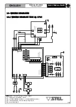
Page 146: ... l Via del Progresso n 59 36020 Loc Castegnero VICENZA ITALY TEL 39 444 639525 central 39 444 639682 comm FAX 39 444 639641 E mail stel stelgroup it http www stelgroup it 14 WIRING DIAGRAMS 14 1 WIRING DIAGRAM MAX dp 171C ENGLISH ELECTRICAL PART ...

Page 147: ...entrazioni elevate di polveri gas infiammabili o vapori combustibili PREVENZIONE CONTRO SHOCK ELETTRICI Prendere le seguenti precauzioni quando si opera con un generatore di corrente tenere puliti se stessi ed i propri vestiti non essere a contatto con parti umide e bagnate quando si opera con il generatore mantenere un isolamento adeguato contro gli shock elettrici Se l operatore deve lavora re i...

Page 148: ...9525 central 39 444 639682 comm FAX 39 444 639641 E mail stel stelgroup it http www stelgroup it 14 3 WIRING DIAGRAM AND CONNECTION FRONT CONNEC TOR PIN1 SENS 2 PIN2 MIN POT COMMUN PIN3 MAX POT PIN4 UP PIN5 REG POT DOWN PIN6 SENS 1 PIN7 CONNECTIONS REMOTE CONNECTIONS TORCH UP DOWN 1 2 3 4 5 6 7 ENGLISH ELECTRICAL PART ...

Page 149: ...DATURA TIG 7 1 PROCEDIMENTI DELLA SALDATURA TIG 7 2 FASI DELLA SALDATURA TIG 8 0 DESCRIZIONE FUNZIONI DI SALDATURA 8 1 SALDATURA AD ELETTRODO 8 2 SALDATURA AD ELETTRODO CELLULOSICO CEL 8 3 SALDATURA TIG 9 0 PREDISPOSIZIONE COMANDO A DISTANZA TORCIA UP DOWN 10 0 V R D 10 1 GESTIONE V R D 10 2 ATTIVAZIONE DEL V R D 10 3 ESCLUSIONE DEL V R D 11 0 FIGURE 11 1 DISTANZA POSTERIORE LATERALI DA MANTENERE ...

Page 150: ...p 171 201C COD 6910700020 STEL s r l Via del Progresso n 59 36020 Loc Castegnero VICENZA ITALY TEL 39 444 639525 central 39 444 639682 comm FAX 39 444 639641 E mail stel stelgroup it http www stelgroup it NOTES ...

Page 151: ...armonisierten Normen angewandt wurden asimismo declara que se han aplicado las siguientes normas armonizadas QUALSIASI MODIFICA ALLA MACCHINA SENZA L AUTORIZZAZIONE DI STEL s r l RENDERÀ NULLA QUESTA DICHIARAZIONE ANY MODIFICATION OF THE MACHINE WITHOUT THE AUTHORISATION OF STEL s r l RENDERS THIS DECLARATION VOID TOUTE MODIFICATION APPORTÉE À LA MACHINE SANS L AUTORISATION DE STEL s r l ANNULERA ...

Page 152: ......

Reviews: