background image

Stellar

®

 TM7120 TireMan Owner’s Manual  |  Page 5

Hydraulic Installation

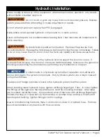
Never modify or alter any of the equipment, whether mechanical, electrical, or hydraulic, 
without Stellar Industries’ approval.


Do not touch or grab any hoses that could be under pressure.  Release 

system pressure before attempting to make adjustments or repairs.

Do not attempt service or repair when PTO is engaged.

Disassemble and assemble hydraulic components on a clean surface.

Clean all metal parts in a nonflammable cleaning fluid.  Then lubricate all components to 
aid in assembly.


Hydraulic fluid expands when heated.  This raises the pressure in an 

unventilated tank.  Release the tank pressure before removing the cap completely.  Failure 
to do so may cause the oil to shoot out of the tank very rapidly and cause severe burns.


Do not rely on the hydraulic fluid to support the boom or crane.  If 

hydraulic fluid escapes, the boom or crane can fall immediately.  Make sure the ground or 
blocking is supporting the boom before performing any maintenance or repair. 


Contaminants in a hydraulic system affect operation and will result in 

serious damage to the system components.  Dirty hydraulic systems are a major cause of 
component failures.

If evidence of foreign particles is found in the hydraulic system, flush the system.

When installing metal hydraulic tubes, tighten all fittings finger tight.  Then , in order, tighten 
the fittings at the rigid end, the adjustable end, and the mounting brackets.  After tubes 
are mounted, install the hoses.  Connect both ends of the hose with all fittings finger tight.  
Position the hose so it does not rub the machine or another hose and has a minimum of 
bending and twisting.  Tighten fittings in both couplings.

Due to manufacturing methods, there is a natural curvature to a hydralic hose.  The hose 
should be installed so any bend is with this curvature.

WARNING

WARNING

WARNING

NOTICE

Summary of Contents for TireMan 7120

Page 1: ...ax 641 923 2811 www stellarindustries com Subject to Change without Notification 2016 Stellar Industries Inc Last Revision 11 28 16 Installation Assembly Drawings Parts Notice A copy of this manual must remain with the equipment at all times For a printable download copy please visit www stellarindustries com ...

Page 2: ...Page ii Stellar TM7120 TireMan Owner s Manual Model TM7120 Manual Revisions Date of Revsion Section Revised Description of Revision ...

Page 3: ...5 Hydraulic Pressure Settings 6 Face Seal O Ring Size Chart 6 Hydraulic Kit FP Version PN 78071 7 Hydraulic Kit RP Version PN 78019 8 Hydraulic Kit CRP Version PN 78012 9 TM7120 FP Version Breakdown PN 77857 10 TM7120 FP Version Bill PN 77857 11 TM7120 RP Version Breakdown PN 74244 12 TM7120 RP Version Bill PN 74244 13 TM7120 CRP Version Breakdown PN 76339 14 TM7120 CRP Version Bill PN 76339 15 De...

Page 4: ...r to the Large OTR Crane Manual for details on these items This manual is not binding Stellar Industries Inc reserves the right to change at any time any or all of the items components and parts deemed necessary for product improvement or commercial production purposes This right is kept with no requirement or obligation for immediate mandatory updating of this manual In closing If more informatio...

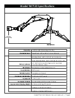
Page 5: ...ncorporated with the crane controls Approximate Shipping Weight 2 750 lbs 1 247 kg FP Version 3 300 lbs 1 497 kg RP Version 3 450 lbs 1 565 kg CRP Version Model TM7120 Specifications Capacity 7 200 lbs 20 ft 3 265 kg 6 10m Clamping Span 49 to 124 124 cm to 314 cm Clamp Cylinders 3 5 8 9 cm bore with integral pilot operated counterbalance valves Tilt Cylinder Provided by crane extension boom Body R...

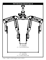
Page 6: ...Page 2 Stellar TM7120 TireMan Owner s Manual 125 Fixed Pads 125 Rotating Pads 123 Continuous Rotating Pads 28 Fixed Pads 28 Rotating Pads 26 Continuous Rotating Pads TM7120 Dimensional Layout ...

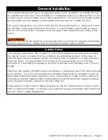
Page 7: ...tional Traffic and Motor Vehicle Safety Act Please reference the Code of Federal Regulations title 49 Transportation Volume 5 400 999 for further information or visit http www gpoaccess gov nara index html for the full text of Code of Federal Regulations General Installation This chapter is designed to serve as a general guide for the installation of a Stellar TM7120 on a Stellar Service Crane Eac...

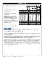
Page 8: ...ed these should only be tightened to the strength of the original Tighten plastic insert or crimped steel type lock nuts to approximately 110 percent of the dry torque values shown in the chart below applied to the nut not to the bolt head Tighten toothed or serrated type lock nuts to the full torque value Note Lubricated means coated with a lubricant such as engine oil or fasteners with phosphate...

Page 9: ...ort the boom or crane If hydraulic fluid escapes the boom or crane can fall immediately Make sure the ground or blocking is supporting the boom before performing any maintenance or repair Contaminants in a hydraulic system affect operation and will result in serious damage to the system components Dirty hydraulic systems are a major cause of component failures If evidence of foreign particles is f...

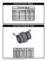
Page 10: ...400 2200 Outer 10 6 4400 2200 Extension 10 6 4400 4400 Rotation 10 6 2200 2200 TM Rot 6 6 2200 2200 TM Pad Rot 6 6 2500 2500 TM Clamp 6 6 4200 4200 Face Seal A Stellar PN Hose Size Fitting Size Stellar PN O ring Boss B 4 C2027 D1245 6 C2028 D1246 8 C2029 D1247 10 32223 D1248 12 D1244 D1249 16 1 3 4 5 8 1 2 3 8 1 4 D1250 B A Face Seal O Ring Size Chart ...

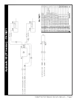
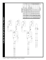
Page 11: ...Stellar TM7120 TireMan Owner s Manual Page 7 Hydraulic Kit FP Version PN 78071 PN 78071 ...

Page 12: ...Page 8 Stellar TM7120 TireMan Owner s Manual Hydraulic Kit RP Version PN 78019 PN 78019 ...

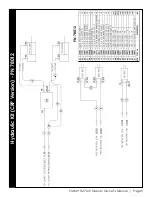
Page 13: ...Stellar TM7120 TireMan Owner s Manual Page 9 Hydraulic Kit CRP Version PN 78012 PN 78012 ...

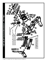
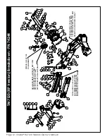
Page 14: ...23 12 31 10 15 8 24 25 9 12 31 10 26 7 9 12 31 10 15 8 2 3 1 13 14 5 35 4 19 17 CHECK OIL LEVEL 27 14 13 12 31 11 16 30 12 31 22 16 36 4 6 12 31 22 16 30 16 11 31 12 30 20 5 4 8 21 5 4 29 34 32 1 3 3 38 37 3 37 OUTPUT SHAFT KIT 68667 OUTPUT SHAFT SEAL KIT 68663 C BALANCE VALVE C6184 CYLINDER SEAL KIT 80989 CYLINDER BUSHINGS 4381 BUSHINGS INCLUDED IN 74351 ...

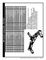
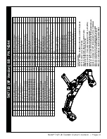
Page 15: ...5CR PIN TEAR DROP 2 50X11 81 3 1 2 V 0 2 1 7 M T Y D O B 5 4 2 4 7 3 2 4 2 V 0 2 1 7 M T K N I L 5 4 3 4 7 4 2 2 5 2 3 1 X 0 5 3 R E D N I L Y C 1 5 3 4 7 5 2 4 T D 3 6 0 1 X 0 0 2 N I P R C 0 5 6 4 7 6 2 1 2 V 0 2 1 7 M T E S A B 2 9 0 5 7 7 2 2 2 V 0 2 1 7 M T M R A 2 6 7 6 7 8 2 1 2 V 0 2 1 7 M T E B U T R E V O C 4 1 0 8 7 9 2 2 1 T H G I A R T S T P N 8 1 K R E Z 2 9 5 1 c 0 3 31 D0790 WASHER...

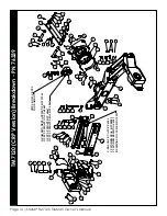
Page 16: ... 9 11 14 37 12 18 10 1 3 47 16 17 6 41 5 22 20 43 34 17 16 14 37 13 19 36 14 37 46 19 42 5 7 14 GEAR BOX REPLACEMENT KIT 39965 46 19 36 19 13 37 14 36 23 6 5 12 37 14 6 5 35 25 38 40 3 43 OUTPUT SHAFT KIT 68667 OUTPUT SHAFT SEAL KIT 68663 BUSHINGS INCLUDED IN 74351 CYLINDER BUSHINGS 4381 CYLINDER SEAL KIT 80989 C BALANCE VALVE C6184 C BALANCE VALVE C6184 CYLINDER SEAL KIT 20632 CYLINDER BUSHINGS 4...

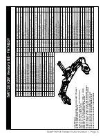
Page 17: ...19 PAD TM7120 CS ROT PADS 1 1 2 V 0 2 1 7 M T Y D O B 5 4 2 4 7 8 2 4 2 V 0 2 1 7 M T K N I L 5 4 3 4 7 9 2 30 74347 ARM TM7120 CS PAD ROT V2 1 31 74348 ARM TM7120 SS PAD ROT V2 1 2 5 2 3 1 X 0 5 3 R E D N I L Y C 1 5 3 4 7 2 3 4 T D 3 6 0 1 X 0 0 2 N I P R C 0 5 6 4 7 3 3 1 2 V 0 2 1 7 M T E S A B 2 9 0 5 7 4 3 1 2 V 0 2 1 7 M T E B U T R E V O C 4 1 0 8 7 5 3 4 1 T H G I A R T S T P N 8 1 K R E ...

Page 18: ...L 5 5 52 13 39 11 29 8 10 13 39 11 17 9 15 16 6 47 5 21 19 55 30 16 15 13 39 12 18 34 13 39 49 18 48 5 7 13 39 49 18 34 18 12 39 13 34 22 6 5 46 14 28 33 31 42 23 25 32 40 38 34 10 14 58 6 5 43 41 2 1 45 24 34 37 36 35 56 57 3 3 3 1 55 CYLINDER BUSHINGS 4381 BUSHINGS INCLUDED IN 74351 GEAR BOX REPLACEMENT KIT 39965 OUTPUT SHAFT ONLY 68662 OUTPUT SHAFT KIT 68667 OUTPUT SHAFT SEAL KIT 68663 ...

Page 19: ...1 6 7 2 3 33 76755 BEARING SWING DRIVE 9 IN ENCLOSED KINEMATICS 2 4 1 T H G I A R T S T P N 8 1 K R E Z 2 9 5 1 c 4 3 35 C2239 FTG 2 2 MP FP STREET ELBOW 90 2 36 C2250 FTG 2 2X1 50 MP MP NIPPLE STRAIGHT BLK 2 2 3 1 0 E P I P R L P C G T F 6 5 2 2 C 7 3 38 C6021 CAP SCR 0 25 20X0 75 BTNHD SS 8 39 D0790 WASHER 0 50 SAE FLAT YELLOW GR8 30 8 S S T A L F 5 2 0 R E H S A W 7 1 9 0 D 0 4 41 D1307 CAP SCR...

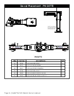
Page 20: ...Rev Level Date By Last Revision 54599 DECAL IDENTIFICATION TM7120 2 53850 DECAL STELLAR LOGO 4 00X11 5 2 22617 DECAL ROTATION BEARING 1 54782 DECAL RATED LOAD 2 54769 DECAL RATED LOAD 2 22618 DECAL GREASE WEEKLY 2 05 06 03 04 01 ITEM PART NO DESCRIPTION QTY 02 PN 54772 6 5 ...

Page 21: ...Stellar TM7120 TireMan Owner s Manual Page 17 ...

Page 22: ...Subject to Change without Notification 2016 Stellar Industries Inc ...

Reviews: