background image

INSSTE302P0514

4

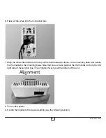
thermostat mounting and connection

1.   

 Cut off power supply on lead wires at the electrical panel in order to avoid any risk of electric 

shock.

2.  Ensure that the air vents of the thermostat are clean and clear of any obstruction.
3.  Using a screwdriver, loosen the screw retaining the mounting base of the thermostat until it is loose  

(do not completely remove the screw).

Then,  remove  the  mounting  base  at  the  back  of  the  thermostat  by  pushing  it  downwards  and  then 

towards you.
4.  Align and secure the mounting base to the connection box using the two screws supplied.

Summary of Contents for STE302P

Page 1: ...mation or to consult this guide online please visit our website at www stelpro com User s guide STE302P Multiple programming Electronic thermostat Energy Verified S Y S T M E Q U A L I T C ERTIFI REGI...

Page 2: ...t this product to a supply source other than 120 VAC or 240 VAC and do not exceed the load limits specified Protect the heating system with the appropriate circuit breaker or fuse You must regularly c...

Page 3: ...th a resistive load 300 W 240 VAC and 150 W 120 VAC and central heating system Parts supplied one 1 thermostat wall mounting plate located at the back of the thermostat two 2 mounting screws two 2 sol...

Page 4: ...f the thermostat are clean and clear of any obstruction 3 Using a screwdriver loosen the screw retaining the mounting base of the thermostat until it is loose do not completely remove the screw Then r...

Page 5: ...them using the supplied solderless connectors When making the connection with aluminum wire make sure that you are using connectors identified CO AL Please note that the thermostat wires do not have p...

Page 6: ...with those on the mounting base and secure the thermostat to the mounting base Note that you can also position the thermostat on the left or the right side of the junction box Then tighten the screw a...

Page 7: ...ermostat is initially in degrees Celsius in Preprogrammed mode preprogramming 5 and the Anticipated start mode is activated The clock is adjusted to Saturday 12 00 and flashes to indicate that an adju...

Page 8: ...ns during 1 minute In case of a power failure lasting less than 2 hours the thermostat saves the adjustment of the hour and the day of the week When the power is restored after an extensive failure th...

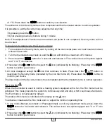
Page 9: ...e it To quickly scroll through the set point values press and hold down the button The standard factory set point adjustment is 21 C From this mode the screen displays the temperature the heating powe...

Page 10: ...t point temperature of the period is flashing Adjust the set point using the and buttons Confirm your selection by pressing down the button 5 The programming of this period is over The programming of...

Page 11: ...our the day of the week and the number of the preprogramming period to displayed on the right hand side of the hour This mode is initially activated when the power is turned on for the first time with...

Page 12: ...observation of the temperature variations in the room and the results obtained during the preceding anticipated starts That way the results should be increasingly precise day after day The icon will b...

Page 13: ...sired preprogramming Preprogrammed more 1 In any mode Manual Automatic or Preprogrammed out of any adjustment mode press down the button for 3 seconds and release it The various icons and options appe...

Page 14: ...flashing Press down the button to confirm your choice 5 All icons disappear except the icon that continues to flash Press down the or button to deactivate the Security mode indicated by the icon that...

Page 15: ...aving and power failures The thermostat saves some parameters in a non volatile memory to be able to recover them after being shut off a power failure for example These parameters are the operation mo...

Page 16: ...sed to maintain the temperature at the set point is expressed as a percentage indicated by the number of bars in the thermometer displayed The heating power used is displayed as follows 4 bars 76 to 1...

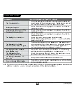
Page 17: ...isplay turns off a few minutes and then turns on again The thermal protection of the heating unit has opened due to overheating Check if the heating unit is in good condition of operation and that cle...

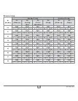
Page 18: ...m 10pm 6am 10pm 21 C 70 F 16 5 C 62 F 21 C 70 F 16 5 C 62 F 21 C 70 F 16 5 C 62 F 3 6am 8am 6pm 10pm 6am 10pm 21 C 70 F 16 5 C 62 F 21 C 70 F 16 5 C 62 F 21 C 70 F 16 5 C 62 F 4 7am 9am 4pm 11pm 7am 1...

Page 19: ...62 F 21 C 70 F 16 5 C 62 F 13 7am 9am 4pm 10pm 7am 10pm 21 C 70 F 16 5 C 62 F 21 C 70 F 16 5 C 62 F 21 C 70 F 16 5 C 62 F 14 7am 9am 5pm 10pm 7am 10pm 21 C 70 F 16 5 C 62 F 21 C 70 F 16 5 C 62 F 21 C...

Page 20: ...unit has a 3 year warranty If at any time during this period the unit becomes defective it must be returned to its place of purchase with the invoice copy or simply contact our customer service depart...

Reviews: