63
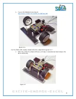
Figure 6.11
11.
Connect the motor controller to the STEM Board as shown in Figure 6.12. The connections
between the STEM Board and H-Bridge should be as follows:
a.
STEM Board Pin 3 will go to H-Bridge Pin 3
b.
STEM Board Pin 5 will go to H-Bridge Pin 4
c.
STEM Board Pin 6 will go to H-Bridge Pin 5
d.
STEM Board Pin 11 will go to H-Bridge Pin 6
Summary of Contents for Pi-Bot v2.00
Page 67: ...67 Figure 6 15 ...
Page 78: ...78 UltraSonicSensorTestwithLED Program ...
Page 80: ...80 ObstacleAvoidance Program ...
Page 82: ...82 ObstacleAvoidancewithLED Program ...
Page 83: ...83 ObstacleAvoidancewithLED Program CONTINUED ...
Page 90: ...90 Download and run the following program LineFollowing Program ...
Page 91: ...91 LineFollowing Program CONTINUED ...
Page 94: ...94 AdvancedLineFollowing Program CONTINUED ...
Page 95: ...95 AdvancedLineFollowing Program CONTINUED ...
Page 96: ...96 AdvancedLineFollowing Program CONTINUED ...
Page 110: ...Appendix B Complete Pi Bot Wiring Schematic ...


