


20
Fig.
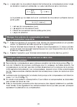
Take out the removal piece (3). With the use of a suitable device, shift the expansi-
on joints (1) from the neutral position to such an extent until the construction gap
(5) is closed. Screw-connect the construction gap (5) as required.
Fig.
Repeat procedure for removal piece (4) – as described under 2.
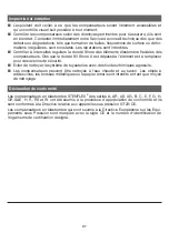
Instructions for rubber-type expansion joints at pumps
Q
Connect the expansion joints as close as possible to the pump flange (
Fig.
).
Q
When using centrifugal pumps for the delivery of abrasive media, the expansion joints
shall not be arranged directly at the pump nozzle (suction-/discharge side). There is
otherwise the danger that the expansion joints will be damaged as a result of the high
relative velocities from vortex and turbulence formation at the pump nozzles.
Q
The installation clearance from pump nozzle to expansion joint shall be 1 x 1.5 DN
(
Fig.
).
Q
With sub-atmospheric pressure on the suction side, a rubber-type expansion joint with
vacuum back-up ring must be applied.
Q
The operation of pumps against fully or partially closed gate/slide valves or dampers
must be avoided. Cavitation should also be avoided because this can lead on a short-
term basis to a destruction of the expansion joint.
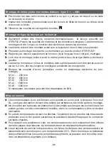
Installation of split back-up flanges / Type C-1, DN
*
2400
Q
Both flange halves must be pre-mounted in such a way that there is no misalignment or
gap at the separation line.
Q
Use suitable and stable washers underneath the nuts/screw heads in the flange separa-
ting area.
Q
Ensure for correct bolting torques.
ꔴ
L
Installation of tie rods / on the builder’s part
Q
Only the tie rods, spherical disks, conical seats and nuts in the required material qualities
and dimensions as specified and prescribed by STENFLEX
®
shall be installed. These
structural elements have been designed to comply with the pre-specified operating con-
ditions.
Q
The tie rods must be installed before pressure is applied to the line.
Q
Perform the installation of the tie rods according to the STENFLEX
®
product drawing.
Q
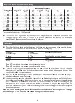
Set the tensioning exactly to the constructional length (pre-Installation).
Q
During pre-installation, make sure that there is the same projection of the threaded rods
right and left.
Q
The tie rod joints (spherical disks/conical seats) must be installed frictionally-locked,
however with a suitable clearance (0.2 mm), so that slight movement is possible.
Q
Lock the nut couples (securement against independent loosening of the threaded union).
M 24 - 250 Nm
M 30 - 500 Nm
M 36 - 700 Nm
M 42 - 1000 Nm
M 48 - 1300 Nm
The values can be exceeded, as necessary, by 50%.
ꔴ
M
Summary of Contents for A Series
Page 2: ...2 ꔴ A ꔴ A 9 9 9 9 10 11 12 ...
Page 3: ...3 ꔴ B ꔴ M 3 3 3 3 2 3 3 FFP F1 F2 F3 ...
Page 4: ...4 ꔴ C ꔴ D ...
Page 76: ......


