background image

www.vingtor.com


STENTOFON and VINGTOR products are developed and marketed by Zenitel Norway AS. The company’s Quality Assurance System is certified to meet the requirements in NS-EN ISO 9001:2002. 
Zenitel Norway AS reserves the right to modify designs and alter specifications without prior notice, in pursuance of a policy of continuous improvement. © 2009 Zenitel Norway AS.

support@vingtor.com

DOC NO


MI 23614 v.1.2                                                              - 8 -                                                                                               GB

2009-09-01

Power supply, LBB 7102/60

The power supply is connected to a 230 V a.c. mains power outlet. This supply cannot be set for other mains voltages. A 
12 V d.c. /500 ma supply must then be obtained locally.
The 12 V d.c. is connected to a screw terminal inside the station.
Up to 5 operator’s units can be powered from one supply.

gooseneck microphone, LBB 7026/71

Mount the optional gooseneck microphone to improve the signal/
noise level on the public side.

 

Break out the tinted field between the buttons and the loud 


speaker.


Route the microphone cable through the opening, the spacer,  


lock washer and nut. Tighten the nut on the microphone  


threaded stud.

 

Insert the microphone plug in connector P9.

 

Close the solder-split N3 to activate the gooseneck microphone  


function.

  By pushing the yellow button you can toggle between built-in  

• 

  and gooseneck mic. The LED is lit when gooseneck is selected.
  The gooseneck mic. can also be mounted on a separate stand.  

• 

  The cable is then routed through the left breakout in the  
  station’s rear cover.

Further instructions are given in the manual MI 23813.

Handset with cradle kit, LBB 7073/82

The standard intercom handset with cradle kit can be connected to 
obtain low-speaking open duplex in heavy noise environments or for 
confidential conversation on the operator’s side.

 

Mount the cradle to the wall by two screws or to the station by  


using a cradle bracket LBB 7073/84, see instruction.

 

Remove the left breakout in the station rear cover.

Summary of Contents for LBB 7026/65

Page 1: ...mounting guide bi way starter kit lbb 7026 65 2009 09 01 MI 23614 v 1 2 ...

Page 2: ... aid radiator Area of Application Bi Way is ideal for areas where security from violence and vandalism is essential or where noise or health problems are of importance such as Cash counters in banks and post offices Embassies Petrol stations Gates and doors to restricted areas Ticket counters in railway stations and airports Treatment labs and isolation wards in hospitals Bi Way Units Bi Way start...

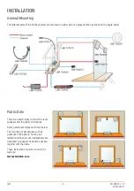
Page 3: ...ral ways to mount the loud speakers and the public microphone Some general examples are shown below The mounting of accessories such as gooseneck microphone hearing aid radiator and flush mount loudspeakers are described in separate instructions packed together with the items These instructions are also found on the web site www stentofon com GB 3 MI 23614 v 1 2 2009 09 01 ...

Page 4: ...the slot at the base or through the holes in the rear Drill a hole in the cabinet for the cable according to loudspeaker placement and fastening method Drill a corresponding hole in the wall for the loudspeaker cable You may choose to drill one hole for each item or select a convenient place for a common hole including the microphone cable Route the loudspeaker cable through the wall from the oper...

Page 5: ...By using one screw through the middle hole B the microphone Snap the microphone onto the base 2 Attach one part of the Velcro pad to either the base plate or directly on the microphone base Clean the glass with an alco pad and press the other part of the Velcro pad to the glass Press the microphone on place Drill a hole in the wall in a convenient place and route the cable through the hole into th...

Page 6: ... Connections Route the switch power cable s from the detector through one of the sta tion breakouts and secure by a strain relief Connect the n o switch cable to P12 1 and P12 4 and the detector power cable to P1 5 and P1 6 Operation Place the operator s unit in standby mode push the green button The movement detector will switch to operating mode when activated The standby mode must be reestablis...

Page 7: ...length of cable to the unit from the public loudspeaker microphone and power for alternative positions on the desk Wall Mounting There are two keyhole openings in the station s rear cover Use screws through these holes to mount the station to the wall Flush Mounting Mount the flush mount frame LBB 7073 70 to the station front and make a cut out in the desk or wall as described in the instruction T...

Page 8: ...al noise level on the public side Break out the tinted field between the buttons and the loud speaker Route the microphone cable through the opening the spacer lock washer and nut Tighten the nut on the microphone threaded stud Insert the microphone plug in connector P9 Close the solder split N3 to activate the gooseneck microphone function By pushing the yellow button you can toggle between built...

Page 9: ...e between high and low speaking mode Further instructions are found in manual MI 24413 External microphone LBB 7026 73 A freestanding microphone with flexible mounting may substitute the built in microphone where the distance to the opera tor s unit is too far This microphone is plugged into connector P4 Further instructions are found in manual MI 23914 ADJUSTMENTS The volume in the operator s uni...

Page 10: ...ange 150 12000 Hz 6dB Dimensions L x H x D 43 x 24 x 12 mm Sensitivity at 1000 Hz 13 5 mV Pa 37 dBV Shielded cable 5 m LBB 7026 80 BI WAY LOUDSPEAKER KIT 2 cabinets silver brown ABS plastic Dimensions WxHxD each 105 x 106 x 62 mm Weight each 180 g Loudspeaker element Philips AD 3071 Y50 Power capacity 2 W max Impedance 50 ohms Cable length total 10 m LBB 7102 60 POWER SUPPLY Dimensions WxHxD 100 x...

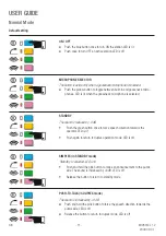
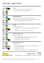
Page 11: ...ECTOR The button is active only when a gooseneck microphone is mounted Push the yellow button to toggle between built in and gooseneck micro phones LED is lit when the gooseneck microphone is selected STANDBY The sound is reduced by 6 dB Push the green button once to force speech direction towards the operator LED is lit Push again to return to duplex operation mode LED is off SIMPLEX in STANDBY m...

Page 12: ...r LED is lit Push again to return to duplex operation mode LED is off SIMPLEX in STANDBY mode Standby is selected LED is lit Push and hold the pink button to make an announcement to the public side The sound is increased by 6dB LED is off Release the button to return to standby mode USER GUIDE Simplex Mode SIMPLEX from DUPLEX mode Standby LED is off Push and hold the pink button to force speech di...

Reviews: