background image


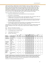
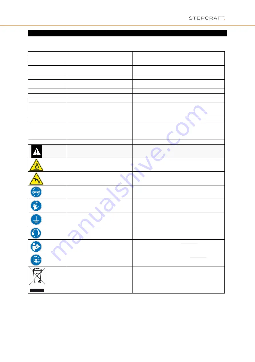
Symbols 


IMPORTANT: 

Some of the following symbols may be used on your tool. Please study them and learn their 

meaning. Proper interpretation of these symbols will allow you to operate the tool better and safer.


Symbol 

Name 

Designation / Explanation 

Volts 

Voltage (potential) 

Amperes 

Current 

Hz 

Hertz 

Frequency (cycles per second) 

Watt 

Power 

Kg 

Kilograms 

Weight 

Min 

Minutes 

Time 

Seconds 

Time 

mm 

Length, Height, Width 

Size in millimeter (metric) 

inch 

Length, Height, Width 

Size in inch 

Ø 

Diameter 

Size of drill bits, end mills, etc. 

…/min 

Revolutions or reciprocation per 

minute 

Revolutions, turns, etc. per minute 

V

, V


Speed 

Horizontal / vertical speed in millimeter per second 

Display off position 

Zero speed / revolution per minute 

15, 45, 75, 99 

Display selector settings 

Speed / revolution per minute as percentage share 

of the max. speed / revolution. Higher number 

means greater speed. 99 equal the max. revolution 

per minute. 


Arrow 

Action in the direction of an arrow 


Warning symbol 

Alerts user to warning messages 


CAUTION hot surface 

Alerts user not to touch the surface – danger of 

burns  


CAUTION rotating tool 

Alerts user not to touch the blade / the insertion 

tool - danger of lacerations 


Wear eye protection symbol 

Alerts user to wear protective glasses 


Wear hand protection symbol 

Alerts user to wear protective gloves 


Grounding symbol 

Alerts user to ground the power tool / electrical 

system 


Wear ear protection symbol 

Alerts user to wear a hearing protector 


Read manual symbol 

Alerts user to read manual BEFORE first 

commissioning 


Unplug symbol 

Alerts user to unplug the device BEFORE servicing 

the power tool  


Disposal symbol 

Instructions for disposal of WEEE by users of the 

European Union 


Summary of Contents for 10016

Page 1: ...500 Call for consumer information Customers from outside the U S STEPCRAFT GmbH Co KG An der Beile 2 58708 Menden Germany Phone 0049 2373 179 11 60 E mail info stepcraft systems com Customers from the U S Canada STEPCRAFT Inc 59 Field Street Rear Building Torrington CT 06790 United States Phone 001 203 5561856 E mail info stepcraft us ...

Page 2: ...i professional product for advanced craftsmen with previous experience in the operation of tools such as electric drills routers and computerized tools like CNC routers or 3D printers It must be operated with caution and common sense and requires some basic mechanical ability Failure to operate this product in a safe and responsible manner could result in personal injury or damage to the product o...

Page 3: ...ench or a key left attached to a rotating part of the power tool may result in personal injury Do not overreach Keep proper footing and balance at all times This enables better control of the power tool in unexpected situations NOTICE Dress properly Do not wear loose clothing or jewelry Keep your hair clothing and gloves away from moving parts Loose clothes jewelry or long hair can be caught in mo...

Page 4: ...the spindle Bristles or wires will be discharged from the brush at high speeds can fly apart and cause injury Never use dull or damaged bits Sharp bits must be handled with care Damaged bits can snap during use Dull bits require more force to push the tool possibly causing the bit to break Use clamps to support the workpiece Never hold a workpiece with your hands Inspect your workpiece before cutt...

Page 5: ...ted tool are likely to fail and create a hazard to the operator Use clamps or another practical way to secure and support the workpiece to the machine table Holding the workpiece with your hands leaves it unstable and may lead to loss of control Develop a periodic maintenance schedule for your tool When cleaning a tool be careful not to disassemble any portion of the tool since internal wires may ...

Page 6: ...ay selector settings Speed revolution per minute as percentage share of the max speed revolution Higher number means greater speed 99 equal the max revolution per minute Arrow Action in the direction of an arrow Warning symbol Alerts user to warning messages CAUTION hot surface Alerts user not to touch the surface danger of burns CAUTION rotating tool Alerts user not to touch the blade the inserti...

Page 7: ...gency Stop 12 3 5 Optional Accessories 12 3 5 1 Collets 12 3 5 2 Insertion Tools 12 4 Operator Control Spindle 13 4 1 Operator 13 4 2 Control Unit 13 4 3 Spindle 14 4 4 Replacing the Collets 15 4 5 Emergency stop Switch 15 4 5 1 Operation 15 4 5 2 Testing the Spindle on off and Emergency stop Functionality 16 4 6 Speed and Feed Settings 16 5 Technical Specifications 18 5 1 Dimensions and Weight of...

Page 8: ...8 1 Response to Malfunctions 20 9 Annex 20 9 1 Warranty and Service Contact information 20 9 2 Manufacturer 21 9 3 Type Plate 21 9 4 Copyright 21 9 5 Limited Warranty 21 9 6 Instructions for Disposal of WEEE by Users of the European Union 23 9 7 RoHS 2002 95 EG 23 9 8 EC Declaration of Conformity 24 ...

Page 9: ...HFS or from failure to follow the safety regulations properly see page 2 cont We reserve the right to further develop the spindle as well as the control system 1 2 DESCRIPTION OF COMPONENTS The STEPCRAFT HFS consists of the milling spindle with the firmly attached cabling and a matching controller frequency inverter The spindle has a 43 mm collar as well as an active air cooling system The milling...

Page 10: ... OF THE INDIVIDUAL PARTS OF THE SPINDLE 1 Cable lead 2 Exhaust cover with air outlet openings 3 Air intake openings 4 Shaft lock button 5 43 mm Euro neck intake 6 ER11 collet nut 2 2 DESIGNATION OF THE CONTROLLER COMPONENTS 1 Engine on off LED 2 Engine on off switch 3 Rotational speed manual setting 4 Rotational speed display in 5 Main switch 6 Signal input STEPCRAFT system bus 7 Spindle screw jac...

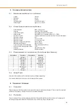
Page 11: ...ndle Humidity should be within the usual levels for indoor environments Protect the spindle against moisture and humidity The ideal temperature of the system is between 18 C and 25 C Especially protect the electronics from overheating by avoiding exposure of the spindle and the controller to direct sunlight or close proximity to a heater Provide adequate lighting for the location of the machine an...

Page 12: ...e emergency stop switch is being pressed This poses a great danger to persons and property If you have any further questions please do not hesitate to contact us For further information on the emergency stop switch refer to item 4 5 of this manual 3 5 OPTIONAL ACCESSORIES If you wish to use accessories not manufactured or sold by STEPCRAFT make sure to check their compatibility with your system pr...

Page 13: ...PERATOR CONTROL SPINDLE 4 1 OPERATOR The improper operation of the spindle and the control unit can cause serious injury and or property damage Read and observe the major accident prevention regulations Each user must have read and understood the available instructions for the entire system machine system held tool control and software before proceeding to operate the device for the first time 4 2...

Page 14: ...and stop the HFS either via command line or the signal test of the control software Please refer to the manual of the control software G code command to start stop the spindle Command Function M03 S5000 Starts the spindle clockwise with a revolution of 5 000 RPM The maximum value for the revolution can be S20000 M05 Stops the spindle 4 3 SPINDLE Never touch the tool This poses a serious risk of in...

Page 15: ...ads to an emergency stop of the machine and the HFS The machine will stop immediately Actuate the emergency stop switch only in emergency situations NOTICE Actuating the emergency stop will result in immediate machine shutdown and can cause step and data losses Controlled cessation of the machine s operation can only be effectuated via the control software To cancel the emergency stop status turn ...

Page 16: ...EPCRAFT Desktop 3D System Mount the spindle on the tensioning system of the machine Switch on the HFS controller an audible confirmation can be heard Do not start the spindle Start the homing sequence of the CNC router STEPCRAFT Desktop 3D System Load the test nc file Jog the gantry to the middle position of each axis X Y Z and save this position as zero position of the imaginary workpiece Start t...

Page 17: ...terial composition Every material has its own characteristics and some materials are hard to cut for example aluminum if it is not an alloy suitable for cutting milling If the insertion tool is not performing as you think it should perhaps you should be using a different accessory and probably an adjustment in speed feed machine setting a play free system is mandatory would solve the problem MID M...

Page 18: ... Labyrinth air cooling Additional features Shaft lock button 5 3 PIN ASSIGNMENT OF THE INTERFACE 15 PIN D SUB INPUT SIGNALS Pin number Function Pin number Function 1 Not used 9 Not used 2 GND mass 10 GND mass 3 Not used 11 Not used 4 Not used 12 Not used 5 Not used 13 Spindle on off 6 Not used 14 Not used 7 PWM Signal 0 5V 15 Not used 8 Not used 5 4 SPARE PARTS All parts of the spindle and the con...

Page 19: ...ance The tool may be cleaned most effectively with compressed dry air Always wear safety googles when cleaning tools with compressed air Make sure to carry out the maintenance care work every 4 working hours Depending on the accumulation of dust and or powdered metal inside the engine s interior has to be cleaned by gently using of compressed air Also clean the collet cone regularly with a fine cl...

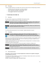
Page 20: ...e device that could cause personal injury or property damage stop the operation immediately using the emergency stop switch NOTICE For less serious malfunctions stop the machine device normally using the controller If you cannot fix the malfunction yourself please contact us specifying the fault which has occurred Our contact details can be found on the front page of this manual 9 ANNEX 9 1 WARRAN...

Page 21: ...ercial or improper use installation operation or maintenance iii modification of or to any part of the product iv attempted service by anyone other than a STEPCRAFT authorized service center v products not purchased from an authorized STEPCRAFT dealer or vi products not compliant with applicable technical regulations OTHER THAN THE EXPRESS WARRANTY ABOVE STEPCRAFT MAKES NO OTHER WARRANTY OR REPRES...

Page 22: ... without additional protection Ship via a carrier that provides tracking and insurance for lost or damaged parcels as STEPCRAFT is not responsible for merchandise until it arrives and is accepted at our facility When calling STEPCRAFT you will be asked to provide your complete name street address e mail address and phone number where you can be reached during business hours When sending products t...

Page 23: ...uipment The separate collection and recycling of your waste equipment at the time of disposal will help to conserve natural resources and ensures that it is recycled in a manner that protects human health and the environment For more information about where you can drop off your waste equipment for recycling please contact your local office your house hold waste disposal or the dealer you purchase...

Page 24: ...24 9 8 EC DECLARATION OF CONFORMITY Copyright STEPCRAFTTM ...

Reviews: