background image


DM556T Digital Stepper Drive User Manual                                                             


Operating Environment 

Environment 

Avoid dust, oil fog and corrosive gases 

Ambient Temperature 

0°C 

  65°C (32°F - 149°F) 

Humidity 

40%RH

90%RH 

Operating Temperature 

0°C 

  50°C (32°F - 122°F) 

Vibration 

10-50Hz / 0.15mm 

Storage Temperature 

-20°C 

  65°C (-4°F - 149°F) 

Weight 

Approx. 300g (10.6oz) 

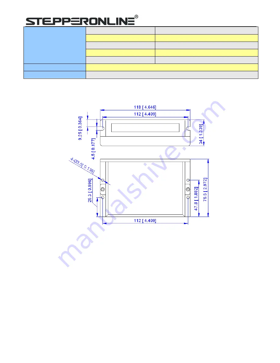
2.3 Mechanical Specifications   


(unit: mm [1inch=25.4mm]) 


Figure 1: Mechanical specifications 

* Side mounting recommended for better heat dissipation 

2.4 Elimination of Heat   


DM556T reliable working temperature should be < 60

 (140°F) 


It is recommended to use automatic idle-current mode to reduce motor heating. That means set the SW4 pin of 
DIP switch at “OFF” position. 


It is recommended to mount the drive vertically to maximize heat sink area. Use forced cooling method to cool if 
necessary. 


Summary of Contents for DM556T

Page 1: ...User s Manual For DM556T 2 Phase Digital Stepper Drive Version 1 0 Designed by StepperOnline 2017 All Rights Reserved Web site www omc stepperonline com E Mail sales stepperonline com ...

Page 2: ...ise without approval from STEPPERONLINE While every precaution has been taken in the preparation of the book STEPPERONLINE assumes no responsibility for errors or omissions Neither is any liability assumed for damages resulting from the use of the information contained herein This document is proprietary information of STEPPERONLINE that is furnished for customer use ONLY Information in this docum...

Page 3: ... Connections of 6 lead Motor 5 5 2 1 Half Coil Configuration 6 5 2 2 Full Coil Configuration 6 5 3 Connections of 8 lead Motor 6 5 3 1 Series Connection 6 5 3 2 Parallel Connection 7 6 Power Supply Selection 7 6 1 Regulated or Unregulated Power Supply 7 6 2 Power Supply Sharing 7 6 3 Selecting Supply Voltage 7 7 DIP Switch Configurations 8 7 1 Microstep Resolution Configurations 8 7 2 Current Conf...

Page 4: ...ut voltage 20 50VDC 16 selectable micro step resolutions of 400 25 600 via DIP switches 8 selectable output current settings of 1 8 5 6A via DIP switches Soft start with no jump when powered on Pulse input frequency up to 200 KHz Automatic idle current reduction Protections for over voltage and over current 1 2 Applications The DM556T stepper drive are designed to power 2 phase 1 8 or 4 phase 0 9 ...

Page 5: ...Approx 300g 10 6oz 2 3 Mechanical Specifications unit mm 1inch 25 4mm Figure 1 Mechanical specifications Side mounting recommended for better heat dissipation 2 4 Elimination of Heat DM556T reliable working temperature should be 60 140 F It is recommended to use automatic idle current mode to reduce motor heating That means set the SW4 pin of DIP switch at OFF position It is recommended to mount t...

Page 6: ...etup time of 5μs Also swapping the connection of two wires of a coil e g A and A to the drive will reverse motor direction DIR ENA Enable signal This signal is used for enabling disabling the drive High level 5V NPN control signal for enabling the drive and low level for disabling the drive PNP and Differential control signals are on the contrary namely Low level for enabling By default it is left...

Page 7: ... In the following figures connections to open collector and PNP signals are illustrated Figure 2 Connections to open collector signal Figure 3 Connections to PNP signal common anode common cathode 5 Motor Connection The DM556T can drive 2 phase and 4 pahse bipolar hybrid stepper motors with 4 6 or 8 wires 5 1 Connections of 4 lead Motor The 4 lead motors are the least flexible and easy to connect ...

Page 8: ...applications where higher torque at lower speed is desired This configuration is also referred to as full copper In full coil mode the motors should be run at only 70 of their rated current to prevent overheating Figure 6 6 lead motor full coil higher torque connections 5 3 Connections of 8 lead Motor 8 lead motors offer a high degree of flexibility to the system designer in that they may be conne...

Page 9: ... and fast response for current change In the case when only normal switching power supplies are available it is important to use OVERSIZE high current output rating power supplies for example using a 4A power supply for 3A stepper motor to avoid problems such as current clamp On the other hand if unregulated supply is used one may use a power supply of lower current rating than that of motor typic...

Page 10: ...N OFF ON 32 6400 OFF ON OFF ON 64 12800 ON OFF OFF ON 128 25600 OFF OFF OFF ON 5 1000 ON ON ON OFF 10 2000 OFF ON ON OFF 20 4000 ON OFF ON OFF 25 5000 OFF OFF ON OFF 40 8000 ON ON OFF OFF 50 10000 OFF ON OFF OFF 100 20000 ON OFF OFF OFF 125 25000 OFF OFF OFF OFF 7 2 Current Configurations For a given motor higher drive current will make the motor to output more torque but at the same time causes m...

Page 11: ...ure itself with the best settings to match the driven stepper motor for optimal performance No action is needed 8 Wiring Notes In order to improve anti interference performance of the drive it is recommended to use twisted pair shield cable To prevent noise incurred in PUL DIR signal pulse direction signal wires and motor wires should not be tied up together It is better to separate them by at lea...

Page 12: ...PUL DIR and ENA should abide by some rules shown as following diagram Figure 10 Sequence chart of control signals Remark a t1 ENA must be ahead of DIR by at least 5 s Usually ENA and ENA are NC not connected See Connector P1 Configurations for more information b t2 DIR must be ahead of PUL effective edge by 5 s to ensure correct direction c t3 Pulse width not less than 2 5 s d t4 Low level width n...

Page 13: ... Troubleshooting In the event that your drive doesn t operate properly the first step is to identify whether the problem is electrical or mechanical in nature The next step is to isolate the system component that is causing the problem As part of this process you may have to disconnect the individual components that make up your system and verify that they operate independently It is important to ...

Page 14: ...s against defects in materials and workmanship for a period of 12 months from shipment out of factory During the warranty period STEPPERONLINE will either at its option repair or replace products which proved to be defective Exclusions The above warranty does not extend to any product damaged by reasons of improper or inadequate handlings by customer improper or inadequate customer wirings unautho...

Reviews: