SteppIR Antennas - 4 Element
10
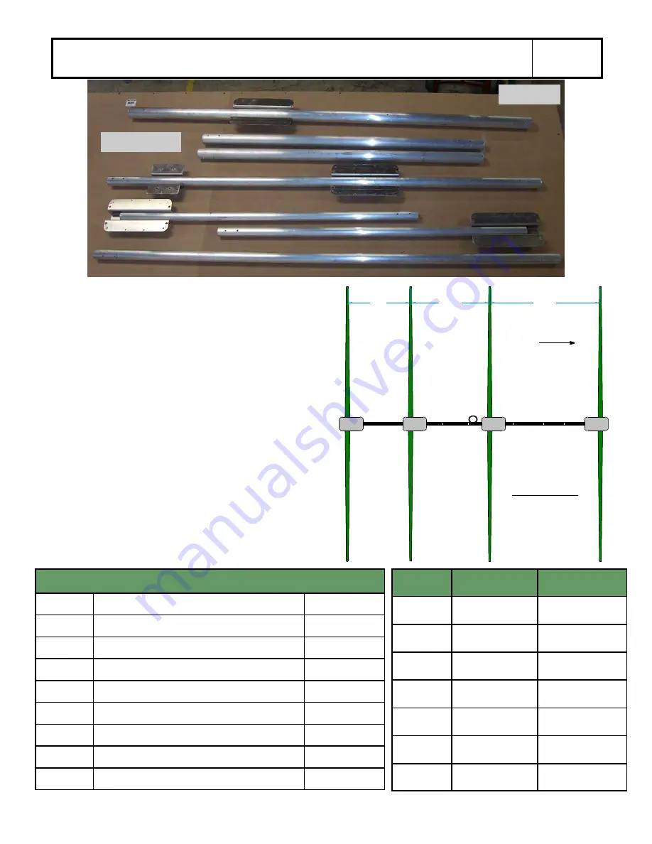
Drawing 1
shows the layout of the boom for assem-
bly. Note that the lengths shown for each boom
piece are overall lengths, the actual finished length of
the boom will be 32 feet. The paired numbers shown
in the drawing are inscribed on each associated boom
section during the manufacturing process. Matching
these numbers will insure correct alignment. Refer
to
Table 2
for proper bolt sizes for each respective
connection.
84
114
182
Reflrctor
Driven
Director 1
Director 2
2 2
3 3
4 4
5 5
6 6
1 1
Mast
Foward
NOT TO SCALE
A
B
C
D
E
F
G
84
114
182
Drawing 1
Table 2: - Bolt Sizes Required for Assembling Boom
Joint
Bolt Size
QTY
1
1/4-20 x 3” w / Nylok nut
1
1*
5/16” x 4” Eyebolt / nut
1
2
1/4-20 x 3-1/4” w /Nylok nut
2
3
1/4-20 x 3-1/2” w / Nylok nut
2
4
1/4-20 x 3-1/2” w / Nylok nut
2
5
1/4-20 x 3-1/4” w / Nylok nut
2
6
1/4-20 x 3” w /Nylok nut
1
6*
5/16” x 4” Eyebolt / nut
1
* The second fastener at this joint is the 5/16” x 4” Eyebolt
used for the truss assembly. (
Figure 3
)
Section
Dimensions
With Bracket
A
1-3/4 x 50-3/8
Yes
B
2 x 72
Yes
C
2.25 x 48
No
D
2.5 x 72
Yes
E
2.25 x 48
No
F
2 x 72
No
G
1-3/4 x 50-3/8
Yes
Figure 1.5
7 Piece Boom
Summary of Contents for 4 Element Yagi
Page 13: ...SteppIR Antennas 4 Element 13 ...
Page 14: ...SteppIR Antennas 4 Element 14 CONNECTING THE CONTROL CABLE TO THE D25 SPLICE ...
Page 15: ...SteppIR Antennas 4 Element 15 ...
Page 16: ...SteppIR Antennas 4 Element 16 ...
Page 34: ...SteppIR Antennas 4 Element 34 ...
Page 35: ......


