2112 116TH AVE NE SUITE 1-5, BELLEVUE WA, 98004 WWW.STEPPIR.COM TEL: (425)-453-1910 FAX: (425)-462-4415
14
•
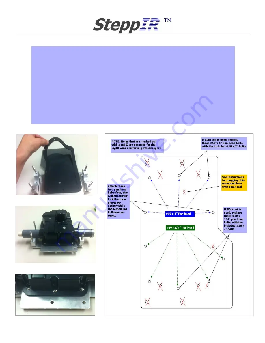
Insert the bottom half of each saddle onto the hex head bolts as shown in figure 8.2. The 2” saddle
half goes on the long side of the reinforcing plate, the 1.75” saddle half goes on the short end.
•
Place the EHU gasket onto the mounting plate as shown in figure 8.2. The inner portion of the gas-
ket material has already been glued to the DB style mounting plate as a guide for the actual gasket.
•
Place the BigIR EHU onto the mounting plate, aligning the holes with the gasket and mounting plate
as shown in figure 8.3 and figure 8.4. Be sure that your 4 conductor control cable is connected in-
side the EHU and properly routed using the cable tray that is molded into the EHU. Refer to figure
8.14 for details.
•
There are two sizes of the #10 pan head bolt that secure the EHU to the DB style mounting plate—
five 3/4” long bolt are used for the portion of the EHU that does not connect to the wind reinforcing
plate and five 1” long bolt used for the portions that connect to the reinforcing plate. NOTE: If you
will be mounting the 80m coil, the four pan head bolts used to secure the coil to the EHU are 2”
Figure 8.3
Figure 8.2
Figure 8.4
Figure 8.5
Wind reinforcing kit installation instructions (continued)
Summary of Contents for BigIR - MK IV Vertical
Page 29: ......


