HLSB-36PCI2 User's Manual
1-2
1.3 Connector specifications
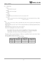
Fig.1-2 Connector peripheral circuit
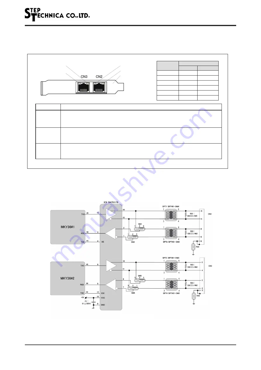
The panel view of HLSB-36PCI2 and its details are shown in Fig.1-1.
CHK1, 2 (Red)
SCAN (Green)
SCAN (Green)
CHK1, 2 (Red)
Panel
Fig.1-1 Panel view
CN2 / CN3 connector peripheral circuit is shown in Fig.1-2.
Panel(F.G.)
Panel(F.G.)
Connection diagram of full-duplex mode
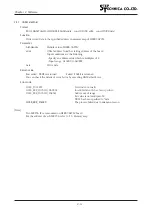
Pin#
Function
Full-duplex Half-duplex
3
RX+
--
4
TX-
TRX-
5
TX+
TRX+
6
RX-
--
8
Shield
Shield
1,2,7
Unused
Unused
SCAN
LED is connected to #SCANL pin of MKY36, lit green when MKY36 is scanning.
CHK1, 2
LED is connected to #CHK1L and #CHK2L pin of MKY36. Lit yellow when CHECK-1 is
occurring, lit red when CHECK-2 is occurring.
LED lit red if CHECK-1 and CHECK-2 are occurring at the same time.
CN2, CN3
HLS communication line
Commercial CAT-5 or more greater straight-through cable for 100BASE-TX can be used.
Be sure that this is not for an Ethernet board.
Panel
Panel is connected to a PC case front panel. Connect a PC case to F.G. in accordance with the PC
manual. Metal shell of CN2 / CN3, and No.8 pin can be connected to the panel by making R33
PAD and R43 PAD on the board shorted. (Refer to Fig.1-2, Fig.1-3.)


