6
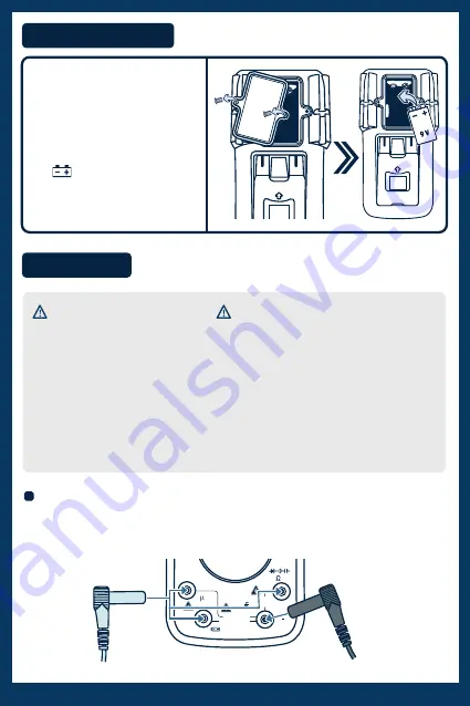
PLACING BATTERY
Remove the screws and the battery
compartment cover using a
screwdriver, and insert a “
9 V
” battery.
Be sure to place the battery polarity
correctly.
If the symbol appears on the screen,
it means that you must replace the
battery.
UP
UP
HOW TO USE
HOW TO CONNECT THE TEST CABLES
Insert the black cable connector into the
COM
terminal.
Insert the red cable connector on the
20 A
,
μA mA
or
V Ω Hz
terminals.
A
T
T
COM
CAT.IV 600V
20A MAX FUSED
400 mA MAX FUSED
CAT.III 1000V
mA
V
20A
MAX 10 SEC.
Hz
SELECT
HOLD
RANGE
REL
Hz
mA
A
A
V
OFF
Hz
(IL 25mA)
Red cable
Black cable
• To avoid the electric shock risk, do not connect the test tips if the Multimeter cover is not in place.
• The selection knob must be in the correct position for the test.
• To avoid electric shock and damage in the Multimeter, do not exceed the maximum values shown in the specifications.
• Never change the knob position of the at random during the measurement.
• To avoid electrical shock or damage in the Multimeter, do not attempt to take any voltage measurements exceeding 60
VDC and 30 VAC.
• The protective fuse must be only replaced by one of the same type and specification.
CAUTIONS DURING USING


