Hold the housing so that it is in contact with the bottom of the joist. Attach the housing with four (4) screws to the joist through
the holes in each mounting flange.
1. MOUNT HOUSING TO JOIST OR I-JOIST.
HANGER
BAR
NAIL
2. MOUNT WITH HANGER BARS
2a. Sliding hanger bars have been provided, which allow the housing to be positioned accurately anywhere between the
framing. The bars span up to 24 in. and can be used on all types of framing: I-joist, standard joist, and truss construction.
Slide hanger bars onto housing and adjust as needed to fit between framing.
2b. Extend the hanger bars to the width of the framing. Position the ventilator with the hanger bar tabs wrapped around the
bottom edge of the framing, holding the ventilator in place.
Secure hanger bars to framing using one screw on each end of hanger bar.
Select a proper hole and secure the hanger bars together using flange screws.
OPERATION
TYPES OF TYPICAL INSTALLATIONS
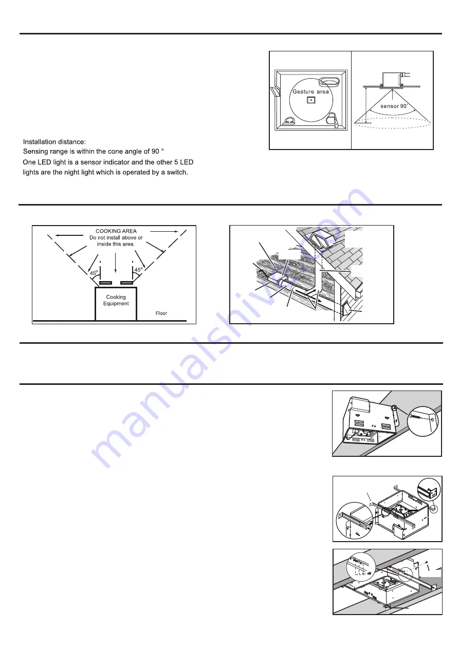
1. Do not use in a cooking area.
2. Two ways to connect ductwork to a factory-shipped unit.
ASSEMBLY INSTRUCTIONS
1. Housing mounted to I-joists (Start at “ASSEMBLY INSTRUCTIONS 1”)
2. Housing mounted to joists (Start at “ASSEMBLY INSTRUCTIONS 1” )
3. Housing mounted to truss (Start at step “ASSEMBLY INSTRUCTIONS 2”)
SCREW
2
ROOF CAP*
(with built-in
damper)
ROUND
DUCT*
WALL CAP*
(with built-in
damper)
*
Purchase
separately
POWER
CABLE*
INSULATION*
(Place around and
over Fan Housing.)
Seal gaps
around
Housing.
FAN
HOUSING
ROUND
ELBOW(S) *
Seal duct
joints with
tape.
Keep duct
runs short
The fan, motion sensor and LED light can be operated
separarely.Sensing distance will be impacted of the body’s own
situation (for example, the thinner people wearing the more remote
sensing distance). Turn on the switch sensor system begins working,
the fan run continuously at a pre-set lower level. When enter the
gesture area fan begins working, indicator light begins flashing. When
persons leave, indicator light turn down, the fan remains working until
the delay time has passed, and then the fan transferred to the low-
speed (you set) operation.
7 to 9 feet
7 to 9 feet.
For model SED110M
PLAN THE INSTALLATION


