Sterling Power Products
Copyright
Copyrights © 1993-2013 Sterling Power Ltd.
All Rights Reserved
Contents Page
Page 2 - About the battery to battery charger.
Page 3 - Annotated diagram of unit, with key.
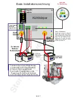
Page 4 - Basic wiring diagram.
Page 5 - Installation
Page 6 - Installation 2
Page 7 - Operational modes
Page 8 - Additional information
Page 9 - Application ideas
Page 10 - Remote control setup
Page 11 - Remote control setup
Page 12 - Custom profile mod. (remote required)
Page 13 - Warranty statement
Battery to Battery Charger series
Background
Thank you for purchasing the most advanced and
powerful battery to battery chargers currently
available in the world today. Please do not
underestimate the affect this device will have on a
conventional DC charging system. It is important to
understand that your existing cables and layout
may
not
be up to dealing with the extra performance from
the alternator. You’ll need to ensure your alternator
cables can deal with the actual rating of the alternator
and the cable run lengths.
Why do I need the Battery to Battery charger?
It is becoming increasingly more common knowledge
now that the best way to charge a battery is using a 4
step battery charging curve. This cannot be achieved
from a standard alternator. This system simply
attaches between 2 battery banks: a starter/engine
battery and a secondary battery (domestic / house)
battery bank. It essentially tricks the alternator into
working at the maximum rating of the charger. This
system is designed to use only the surplus power. It
ensures at all times, that the power required to run the
primary system of the vehicle or boat is not
compromised. This surplus power is converted into a
higher voltage and is used to charge a secondary
battery bank using a digitally controlled
programmable 4 step charging curve. This unit is also
totally isolated, thus, the starter battery cannot
discharge through this system, even in the event of
the unit failing.
How does the unit work?
The unit monitors the engine start battery. This unit
will not start until the battery voltage exceeds about
13.3V (x2 for 24V). After that, it pulls the engine
battery down to no less than 13.3V. This enables the
engine battery to still receive a small charge and
ensures the alternator works at its full potential. The
unit takes the 13.3V into the control box and then
boosts this up to a maximum of 15.5V (selectable
chemistry profiles between 14.0-15.5V - consult
battery manufacturer). A rule of thumb: Higher
voltages result in faster charging and lower voltage
result in slower charging. After a period of time,
calculated by the software, when the auxiliary
batteries are full, the system will float the batteries at
approximately ~ 13.5V (x2 for 24V). It always ensures
the engine battery comes first.
Other features included in this system are battery
temperature sensors, remote battery sensors and a
fully automatic sleep sensor, which switches the unit
off when the engine has stopped. A remote panel is
available as an optional extra.
Advantages of this unit.
1)
Installation:
Simply connect between two battery
banks (e.g. starter and house).
2) No direct connections to the standard engine
alternator or to the outboard. Thus, on new
installations there is no extra wiring for a split
charging system.
3) This unit ensures the engine battery is kept full to
start the vehicle while using as much surplus power
as possible to boost into the auxiliary system.
4)
Multiple units can be
used, for example, if you
have a 100A alternator and 3 battery banks (engine,
domestic, and bow thruster); then, 2 of these can be
used to run the bow thruster and the domestic
system. Their internal programs will adjust their
charging patterns to accept the other unit. The unit
shall ensure only the excess power is used and the
primary system is not placed in jeopardy.
5) Ensures there is no voltage rise on the engine
management system. Likewise, it ensure no alarms
nor damage to the main system - be it an outboard, a
car or a boat.
6) There are
no vehicle warranty issues
as you are
not connected to the main engine management
system.
7) This charger
isolates both battery banks
and
prevents any feedback through the unit.
8)
Compensates for large voltage drops
in long
cable runs with the use of a sense cable.
9) Can both
boost charge
or
voltage reduce
, if
required. Sometimes alternators sustain a voltage
that is too high for the batteries, this unit drops the
voltage down
Current limiting feature
The ability to
current limit
is
a very important aspect
of this product's design. Being able to limit the current
to the rating of the product (60A/120A/240A) is
advantageous as it protects the DC wiring system
from large surges from bow thrusters or large
inverters. These surges can often exceed the rating of
the wires, fuses, relays and diodes in the system
causing permanent damage. If you can limit the
current to 60A, for example, you can rate your relays,
diodes, fuses to 80A. If your inverter / bow thruster
takes a surge of 300A only 60A can be drawn down
Page 2


