background image

14

15

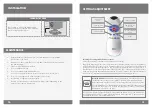
seTTIngs AdjUsTmenT

adjusting the settings with the remote control

If necessary, the sensor settings can be adjusted as following:
Shut off the water supply. In order to adjust the sensor with the remote control, hold the remote 

control straight in front of the sensor in a distance of about 6-8” (15-20cm). choose the function 

you want to adjust by pressing once on one of the function buttons. After pressing once on a 

specific function button, a quick flashing of the LED at the front of the sensor will occur. At this 

stage, you can change the setting by pressing the (+) or the (-) buttons, every push will increase 

or decrease one level. After finishing the adjustment, turn the water supply back on. 

DETEcTION 

rANgE 

DELAY IN TIME

SEcurITY TIME 

DELAY OuT TIME 

TEMPOrArY OFF 

FuNcTION 

rESET

SELF ADJuSTMENT 

MODE

DeteCtIon ranGe:

 This Hand Dryer was supplied with a self adjusting sensor. 

The ideal detection range for the specific location will be set automatically. 
Only if necessary, use the remote control to adjust the sensor range as follows:
Press the rANgE button. Wait until a quick flashing of the LED in the sensor eye 

is perceived. Then, press + to increase the range and – to reduce it. Every push 

will increase or decrease one level. 

Note: Once you have changed the detection range with the remote control, the distance will 

be remembered by the sensor, even if the power source is disconnected. To get back to the 

self adjustment mode, use the ADJ button only.

a. 

regular cleaning of the hand dryer is recommended to ensure optimum  


functioning of the dryer.

b. 

Any access to the dryer will be done only after it has been disconnected from    


the power supply.

c. 

clean the dryer with a damp cloth.

d. 

Do not squeeze the cloth.

e. 

Do not rinse the dryer with a water hose.

f. 

Do not use any material that is worn or scratched (iron, scotch, etc.).

g. 

Do not use any aggressive cleaning agent (acid or base).

h. 

No cleaning is required for internal parts.

i. 

Be sure to clean the motor unit filter every few months (depending on the  


nature of use) replace if necessary.

mAInTenAnCe

InsTALLATIon

CHAngIng THe fILTeR

Press button to release the filter housing. 

remove and clean or replace filter. click the 

filter housing back into place.

press

Summary of Contents for 230510

Page 1: ...TUBULAR ever Hand Dryer I n s t a l l a t i o n a n d m a i n t e n a n c e g u i d e...

Page 2: ...their design are the property of Stern Engineering Ltd or other third parties and you are not permitted to use them without the prior written consent of Stern Engineering Ltd or such third party as ma...

Page 3: ...ears WARNING WARNING RISK OF FIRE OR ELECTRICAL SHOCK All electrical work is to be done in accordance with applicable codes and regulations All electrical work must be done by qualified electricians U...

Page 4: ...16 350040 Tubular HD PACK CONTENTS 1 x Hand dryer and attachments 1 x Hand dryer unit Power supply cord with plug plug is optional according to the region Tubular HD 1 x Allen key 7mm 1 x Allen key 2...

Page 5: ...ubular DP HD AISI 316 350010 1 x Hand dryer and attachments 1 x Hand dryer unit Tubular DP HD 1 x Allen key 7mm 1 x Allen key 2 5mm 1 x Allen key 3mm 4 x Screws Ancors 4 x Screws Ancors Hose 2 clamps...

Page 6: ...chnical data EVER HD 230510 1 x Hand dryer and attachments Hose 2 clamps 1 x Allen key 7mm 1 x Allen key 2 5mm 1 x Allen key 3mm 4 x Screws Ancors 1 x Hand dryer unit Power supply cord with plug plug...

Page 7: ...chors in 3 Secure the base support using the 4 screws make sure that the base is leveled to the center After tiling mount the Tubular body onto the base and thread the cable through the base and air h...

Page 8: ...SIBLE CONNECTED PROPERLY 1 2 9 Reassemble cover knob filter housing Connect the electricity cable not included installation operating the hand dryer Before proceeding check that no objects are in fron...

Page 9: ...adjust the sensor range as follows Press the RANGE button Wait until a quick flashing of the LED in the sensor eye is perceived Then press to increase the range and to reduce it Every push will increa...

Page 10: ...p foam dispenser components including pipes SETTINGS adjustment Entrance to the self adjustment mode Check that no objects are in front of the sensor Press the ADJ button Once a quick flashing of the...

Page 11: ...06 19 01500383 A 777 Passaic Avenue Clifton NJ 07012 USA Tel 1 973 773 8011 Fax 1 973 779 8768 Toll Free 1 800 4364410 info sternfaucets com tech sternfaucets com...

Reviews: