background image

8

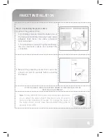
LIMITING THE MAXIMUM TEMPERATURE

The mixer includes an internal temperature stopper that limits the maximum  water 

temperature the user can obtain. The internal stopper  factory setting is 38ºC  and can be 

calibrated from 38ºC to 55ºC.

1

Place the cap in the 38ºC position.

2

Unscrew the faucet cap screws and 

remove the cap without changing the 

position of the spindle.

3

Unscrew the stopper screw partially for 

a medium resistance and locate it on the 

minimum temperature position.

MINIMUM TEMPERATURE 

POSITION

4

Locate the cap in the 38ºC position.

Important: For type 3 valves in healthcare installations, the maximum mixed water 

temperature (defined by the mixer internal stopper) should not exceed the 41°C limit as 

determined by the application. Refer to section: ‘Type 3 valves information’ for more details.

Summary of Contents for Trendy 1000 T

Page 1: ...1 INSTALLATION AND MAINTENANCE GUIDE E L E C T R O N I C L A V A T O R Y F A U C E T TRENDY 1000 T...

Page 2: ...7 ADJUSTING THE MIXED WATER TEMPERATURE 8 9 LIMITING THE MAXIMUM TEMPERATURE 10 TYPE 3 VALVES INFORMATION 12 SETTINGS ADJUSTMENT 13 BATTERY REPLACEMENT BATTERY MODELS ONLY 14 MAINTENANCE Filters clea...

Page 3: ...se a pressure reducing valve Sensor range 170 mm Adjustable with remote control Minimum sensor range 50 mm Maximum sensor range 350 mm Security time 90 seconds Can be reduced with the remote control H...

Page 4: ...o obtain cold water and to the right to obtain hot water MANUAL MIXER To set a desired stable temperature Release the thermostatic mixing cap by unscrewing the M4X6 screw located behind the thermostat...

Page 5: ...PACK CONTENTS Familiarize yourself with the part names and confirm that the parts are included 1x Faucet and attachments 2 x Filters 1x Allen key 9 V Battery box 9 V Transformer B VERSIONS E VERSIONS...

Page 6: ...discarding any packaging material If any parts are missing do not attempt to install your electronic faucet until you obtain the missing parts PREPARATION FOR INSTALLATION Flush water supply lines tho...

Page 7: ...lavatory Make sure the O ring is located between the deck or lavatory and the bottom of the faucet 2 Secure the faucet to deck or lavatory with the hexagonal nut Step 3 Connecting the water supply 1...

Page 8: ...e electricity socket and connect the connectors 2 Remove the protecting sticker that covers the sensor and wait 10 seconds before activating the faucet IF THE RANGE IS UNSATISFACTORY REFER TO THE SECT...

Page 9: ...CORDING TO THE SITE SPECIFIC CONDITIONS 1 Unscrew the faucet cap screws and remove the cap 2 Proceed to achieve a 38 C temperature by turning the spindle and measuring the water temperature with a the...

Page 10: ...s and remove the cap without changing the position of the spindle 3 Unscrew the stopper screw partially for a medium resistance and locate it on the minimum temperature position MINIMUM TEMPERATURE PO...

Page 11: ...um temperature with the help of a thermometer 7 Return the cap to 38 C position and remove it by unscrewing the top and bottom screws Note make sure not to change the spindle position while removing t...

Page 12: ...supply temperatures are within the range permitted for the valve and by guidance information on the prevention of legionella etc 4 Adjust the temperature of the mixed water in accordance with the ins...

Page 13: ...lters are clogged and clean them accordingly refer to section Maintenance filter cleaning instructions c Check that the check valves located in the flexible hoses are in good working conditions Replac...

Page 14: ...ecified in this table following 2 3 in test results with a change in the mixed water temperature no larger than 1 C Commercial TYPE 3 VALVES INFORMATION TEST FREQUENCY Final mixed water temperature Ev...

Page 15: ...te control hold the remote control straight in front of the sensor in a distance of about 6 8 15 20cm Choose the function you want to adjust by pressing once on one of the function buttons After press...

Page 16: ...Press the SEC button Wait until a quick flashing of the red light of the sensor eye is perceived Then press to increase the security time and to reduce it DELAY IN TIME It is recommended to change the...

Page 17: ...le cleaning The faucet will remain shut for 1 minute when this button is pressed once To cancel this function and to return to normal operation press the On Off button again or wait 1 minute RESET BUT...

Page 18: ...de part of the Trendy 1000 body using the 2mm Allen key provided 3 Disassemble the sensor cap 4 Remove the old battery disconnect from the battery connector and take out the battery cover protection 5...

Page 19: ...ing water 4 Reassemble the parts 5 Reconnect the flexible pipes and restore the incoming water supply 6 Make sure that there is no water leakage Care and cleaning of chrome and special finishes DO NOT...

Page 20: ...n the sensor does not flash when user s hands are within the sensor s range Water flow from spout does not stop Decrease the range or eliminate cause of reflection 2 Sensor is picking up reflections f...

Page 21: ...S LIST Sensor Kit Cat No 07220086 Thermostatic cartridge Cat No 07110016 Solenoid valve Cat No 07500065 Battery box Cat No 06530008 Transformer Cat No 06522042 Filter Cat No 08530014 Remote Control Ca...

Page 22: ...price of the faucet valve or control If you believe that you have a warranty claim contact your Stern Distributor Dealer or Plumbing Contractor Please be sure to provide all pertinent information rega...

Page 23: ......

Page 24: ...22 15 Gan Rave Blvd 81222 Gan Rave Yavne Israel Tel 972 8 9326000 Fax 972 8 9326025 export sternfaucets com www sternfaucets com 09 13 01500208 B...

Reviews: