Final Assembly Continued
☐
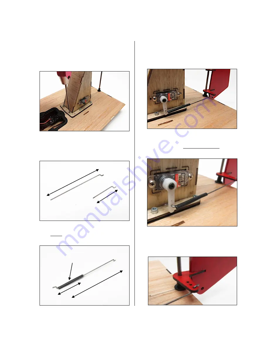
Use a 5/64” hex driver to secure motor mount
to hull using 7 of the provided #2 x 3/8”
socket head screws. Set screws to just snug
mount to gasket surface then apply only 1/2
turn to each screw to mildly compress gasket.
☐
Create the Rudder Control Rod, cut the
provided 1/32” diameter wire into two lengths
1” and 2-3/4”. Now, using small needle nose
pliers, bend a “Z” in one end of each length.
Join the these lengths of wire by overlapping
each
within
a 1” length of heat shrink. Shrink
the tubing with a heat gun to retain parts.
☐
Trim your servo control horn so that when
installed as illustrated it will not drag along the
hull of the boat. Mount the control rod to one
of the outer most holes on both the servo and
the rudder control horns.
With the HS-35HD servo we prefer to use the
long horn, trimmed as illustrated, with the
control rod in the 3rd or 4th hole out from the
servo center.
At the ruder end of the control rod we prefer
the “Z” bend to enter from the bottom as
shown as this nets the best clearance from
the propeller.
Build Instructions
© 2013 Stevens AeroModel all rights reserved.
Page 18 of 25
2-3/4”
1”
1”
2-3/4”
1” Length Heat Shrink


