© 2004 Stevens AeroModel.
Page 16 of 33
19. Key F1 to fuselage spanning fuselage sides and FB1. The fit here may be particularly tight work the parts
together carefully some light sanding of the tabs or notches may be required. Key parts F9 and F10 to
fuselage top decking. Note: F10 slopes towards the front of the fuselage. Secure parts with thin CA.
20.
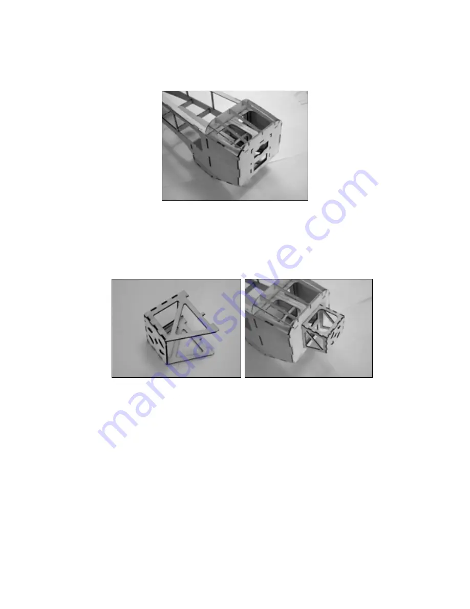
Locate the motor mount parts on the 1/16” ply parts sheet. Note that there are two motor mount faceplates
included on the 1/16” cut ply sheet: MM1 is designed to accommodate the Hacker B20-15L while MM1a was
designed to accommodate the AXI 2808-20. Assemble the motor mount as indicated below – Tack together
using thin CA glue. Key the completed motor mount assembly to the firewall. Note that the tabs on the motor
mount and notches in the firewall may require light sanding. Only take enough material to facilitate the fit. We
want a good snug fit to the fuselage firewall. Once satisfied with the glue the motor mount in-place and flow
thin CA liberally into all motor mount joints.
21.
VERY IMPORTANT! Special Instructions for the AXI 2808-X Series motors.
Locate the 1/32” ply doubler MM1b using 5-minute epoxy or wood glue laminate this doubler to the
face of MM1a.
Spread a thin epoxy fillet along the inside joints of the motor mount MM1a/b to side plate joint.
(THICK CA glue makes for a brittle joint do not use thick CA on the motor mount as a glue fillet.)
The
epoxy fillet will ensure that the mount weathers the normal in-flight vibrations and stresses that the out
runner motor will place on the mount.
NEVER run up an out of balance prop or spinner – at any RPM! NEVER run a prop that is out of
track. NEVER run a prop adapter that is damaged or bent. (Ignoring any of these suggestions may
lead to vibration that may damage the airframe, motor mount, and your electronics)
Disable your prop brake on the ESC (out runner motors and prop brakes are not a good
combination)


