© 2007 Stevens AeroModel.
Page 15 of 35
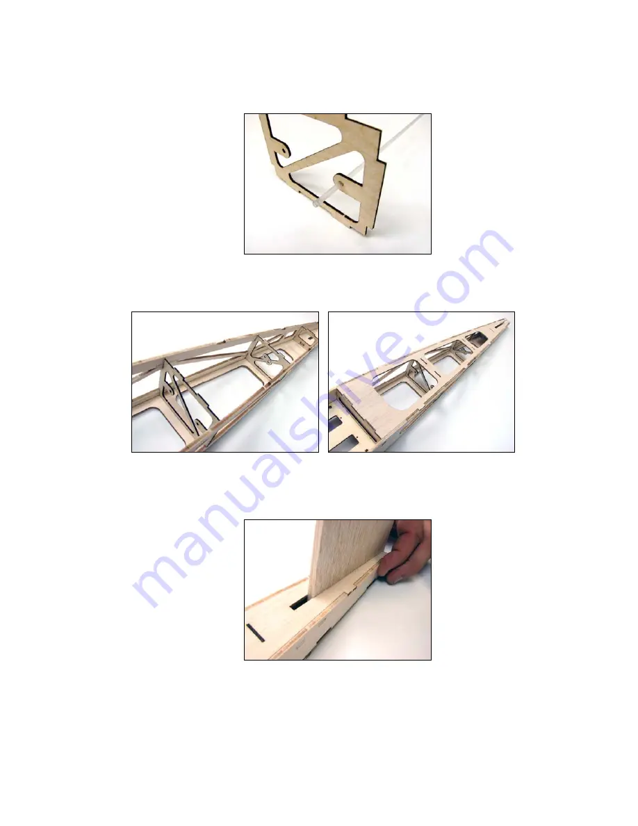
Now is a good time to verify that the push-rod housing will easily fit within the laser cut holes of formers F3, F4,
and F5. Locate the 18” length of plastic .090” diameter pushrod housing and test fit to holes provided in these
formers. Adjust the hole size using a rat-tailed file if necessary.
17. Complete the mid section of the aft fuselage assembly by first installing the 1/16” plywood formers F4 and F5 as
illustrated below. Next, key the 3/32” balsa former F9 to the top of the fuselage assembly spanning formers F3,
F4, F5, F6 and fuselage sides, as illustrated below.
Here’s a neat assembly trick. Use a scrap piece of the 3/16” balsa stock from which your tail surfaces were cut.
Slip this scrap in the slot at the aft end of the fuselage to assist in properly seating the parts at the tail section.
Carefully tack glue the tail section, remove the scrap, then complete the tail with a good application of thin CA
along the inside surfaces. JUST BE CAREFUL NOT TO GLUE THE SCRAP WITHIN THE TAIL SECTION
SLOT!
18.
Final glue all fuselage parts.
For the most part we have been utilizing thin CA glue to hold parts in position
while we complete the fuselage assembly. At this point it’s time to finalize the fuselage by re-visiting every
surface to surface joint with thin CA glue making certain that all parts are securely bonded. Hold you fuselage
flat against your building surface while bonding to ensure that it remains straight.


