background image

© 2007 Stevens AeroModel.  


Page 28 of 35 

Ailerons: 


1. 

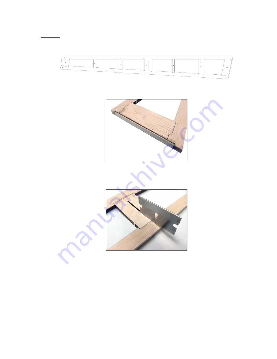
Assemble two (2) ailerons as illustrated below from 3/16” balsa parts A1, A2, A3, A4, A5, A6, A7, A8, and A9. 


2. 

With the balsa ailerons complete locate the 1/16” ply part marked “A10” and install to recessed area of inside 
edge of balsa aileron bordering “A4”.  


3. 

*** OPTIONAL STEP for those wishing to run a split aileron / flap wing system you can cut the ailerons into two 
pieces at A7 (A7 is partially pre-cut for this application) and purchase an additional set of DuBro Micro Razor 
Control horns DUB936 and Auxiliary BEC device to support the additional servo load.  We are simply illustrating 
where we have accommodated this requested feature as running split ailerons is an advanced option for 
experienced modelers and is beyond the scope of this manual. *** 


Summary of Contents for SHAFT25e

Page 1: ... 2007 Stevens AeroModel Page 1 of 35 SHAFT25e Instruction Manual Version 1 01 Span 52 in Length 45 in Area 600 Sq In Weight 32 40 oz ...

Page 2: ...to fly from a smooth dirt or paved surface If you must fly from a turf field run a large diameter narrow wheel and remove wheel pants if equipped WARRANTY Stevens AeroModel guarantees this kit to be free from defects in both material and workmanship at the date of purchase This warranty does not cover any component parts damaged by use or modification In no case shall Stevens AeroModel s liability...

Page 3: ...40 x 1 2 Bolt 4 4 40 x 3 8 Bolt 1 Package Gum Rubber Bands 33 10 2 3 16 Neo Magnet 1 1 4 Dia x 4 3 4 Length Hardwood Dowel 2 3 16 x 4 3 4 Length Hardwood Dowel 1 Laser Cut Basswood Elevator Joiner Recommended Finishing Items 1 2 Rolls of AeroFILM Lite Solarfilm Solite or Nelson Lite Film may be substituted Suggested Electronics 1 4 Micro Servos Hitec HS 81 Requires 2 Additional HS 65 Servos for Fl...

Page 4: ...te set of Horizontal Stabilizer and Elevator for those who prefer the squared off look of the stick plane thus you ll find an extra sheet 17 21 in this kit distribution Remove parts from the sheet with a sharp 11 hobby blade Assemble the parts on top of your plan sheet using the drawings on the sheet to reference part location and orientation Frame up all tail feather components as illustrated bel...

Page 5: ...A glue Assemble F11a and F11b to create one F11 former Assemble F7a F7b and F7c to create one F7 former Assemble H2a H2b and H2c to create one H2 battery hatch component make certain scribe lines running lengthwise along H2 components are on the same side See illustration below and plan set for further reference 2 Assembly of the fuselage crutch begins USE NO GLUE TO BOND THE PARTS UNTIL INSTRUCTE...

Page 6: ...to both sides of the fuselage crutch as illustrated in the photo below 6 Test fit the completed fuselage crutch to one of the 1 8 balsa FS fuselage sides Any failure to follow the proper top side part orientation will be revealed here If the tabs in your fuselage crutch do not align with the notches in the fuselage side you will need to re visit the crutch assembly and pay careful attention to the...

Page 7: ...1 to the forward portion of the crutch and the fuselage sides Wick liberal amounts of thin CA glue along the joints where F1 touches the fuselage assembly Once the thin CA glue has cured build up a small fillet of medium CA glue along the same joints 9 Before the front of the fuselage is sealed up we need to install the balsa cross grain doublers for the forward wing dowel mounts Locate the 3 32 b...

Page 8: ...ace and proceed to glue former F8 in place See second illustration below 12 Locate the 1 16 ply part G2a and 1 32 ply part G2b Glue these on top of each other carefully matching the outer edges to create part G2 Next key the assembled part G2 landing gear re enforcement strap to the notches provided in the underside of the fuselage as illustrated below Retain with thin CA glue followed by and appl...

Page 9: ...lustrated in the first photo below Next key 3 32 balsa part F13 to underside of fuselage atop F12 and spanning fuselage sides and former F3 Make certain that F13 fits flush with fuselage sides and is properly seated at all tab and notch locations Now square your fuselage assembly to your flat work surface and tack glue part F13 into position at all tab and notch locations 16 Before we seal up the ...

Page 10: ...ick Use a scrap piece of the 3 16 balsa stock from which your tail surfaces were cut Slip this scrap in the slot at the aft end of the fuselage to assist in properly seating the parts at the tail section Carefully tack glue the tail section remove the scrap then complete the tail with a good application of thin CA along the inside surfaces JUST BE CAREFUL NOT TO GLUE THE SCRAP WITHIN THE TAIL SECT...

Page 11: ... these to the fuselage using the plan sheet and illustrations below to guide your work 21 Complete assembly by installing the second neo magnet within the assembled catch VERY IMPORTANT Magnets are polarized They will attract with great force and will likewise repel each other with great force if one of the poles is reversed Check to see that magnets stick to each other Tip Mark contacting faces w...

Page 12: ...h rod housing you ll need to remove the push rod exit knock outs which are partially cut and located on either side of the fuselage tail section Use a sharp razor to remove the retention tabs and knock the plugs out 24 Prior to final sanding the model you ll want to Install the two 18 lengths of 090 diameter pushrod tubing First slip the tubing through the aft end of the fuselage through the openi...

Page 13: ...bing flush with the fuselage sides where they exit at the aft end of the fuselage assembly 25 Final sand your fuselage using a sanding block and 400 grit paper Slightly radius the edges of the fuselage and remove any exposed laser burn marks DO NOT sand modify the shape of the wing saddle ...

Page 14: ... builder with mounting and rigging this setup beyond showing you where the parts assemble the builder is on their own with implementing the quad split aileron system at the time of publication Stevens AeroModel does not offer technical assistance for implementing this setup 1 Begin construction by assembling major parts from sub assemblies W1a and W1b to create W1 turbulator with jig W2a and W2b t...

Page 15: ...e second S2 spar cap aside as this will not be joined to the assembly until much later See illustration below 4 OPTIONAL STEP If you plan on running the split aileron setup now or in the future you ll want to remove the circular knock outs in ribs R2 and R3 to allow the outboard aileron servo wires to pass through 5 Fill out the remainder of the wing by installing 3 32 balsa wing ribs R2 R3 R4 and...

Page 16: ...n later upgrade experiment with the quad aileron flap setup For this setup you ll need to locate and install the following parts 1 32 ply SR81a and 1 8 balsa SR81b servo pockets spanning the S1 spar web and rib R2 and parts 1 32 ply SR65a and 1 8 balsa SR65b servo pockets spanning the S1 spar web and rib R4 OPTIONAL SETUP 2 Option 2 is the best option for running the quad flap aileron system as it...

Page 17: ...e first three photos will apply If building the Option 2 setup you ll use the SR65a and SR65b parts contrary to what is illustrated in the first three photos Clear as mud Dry fit the components then double check your work against the servos you ve chosen once satisfied complete the assembly with glue 7 Locate the 1 8 balsa part W6 and bond to the wing center section using the notches in ribs R1 to...

Page 18: ...op of CA glue where it meets the outer wing rib and trailing edge Lay the wing flat on top of your building board Then proceed to tack glue the W3 truss parts at the trailing edge and where they contact the S1 spar and S2 spar cap 10 Locate the 3 32 balsa sub ribs R1a R2a R3a and R4a and key these to the S1 spar web as illustrated below Inspect the fit to make certain that the sub ribs seat flush ...

Page 19: ...of turbulators W1 and W2 will fit flush with the top surface of ribs R1 and R5 Along all mid span ribs R2 through R4 turbulators W1 and W2 will seat proud of the top rib surface by 3 32 Locate a scrap piece of 3 32 balsa and use it to reference the proper installation height of W1 and W2 13 Install the leading edge center section 3 16 balsa parts marked LE1 Both of these parts can be found in the ...

Page 20: ... easily seats in full contact within the leading edge of the wing spanning ribs R1 through R5 bond with thin CA glue 15 Locate the second 1 8 balsa S2 spar cap strip and install to top side of spar web as illustrated below 16 Bond the 1 8 balsa W7 leading edge re enforcements to the notches in rib R1 W7 should make full contact and be centered to the 1 4 balsa wing leading edge stock as illustrate...

Page 21: ...ivor in the hands of novice pilots who may botch a landing or two It s been our experience that bolt on wings do a poor job of weathering such abuse Thus beyond pre cutting provisions for this option a bolt on wing is neither recommended nor supported by Stevens AeroModel 20 DO NOT OVERLOOK THIS STEP YOU MUST FINAL GLUE ALL WING ASSEMBLY PARTS For the most part we have been utilizing thin CA glue ...

Page 22: ...g edge should be sanded flush with the profile of only ribs R1 and R5 and remain proud of the mid span ribs by 3 32 see step 12 and use scrap 3 32 balsa as height a gauge A razor plane makes short work of shaping components such as wing leading and trailing edges we suggest the Master Airscrew MAS4100 razor plane If you do not have the luxury of a 7 razor plane for this project a long sanding bloc...

Page 23: ...4 3 OPTIONAL STEP for those wishing to run a split aileron flap wing system you can cut the ailerons into two pieces at A7 A7 is partially pre cut for this application and purchase an additional set of DuBro Micro Razor Control horns DUB936 and Auxiliary BEC device to support the additional servo load We are simply illustrating where we have accommodated this requested feature as running split ail...

Page 24: ...ith Thin CA 2 Do the same with the 1 4 diameter hardwood dowel for the landing gear mount Round the ends test fit remove and harden holes with Thin CA 3 The photo below illustrates how the landing gear is banded to each side of the 1 4 dowel hard point The method for landing gear attachment is as follows Start one 33 rubber band around 1 4 dowel then wrap around the top loop of the landing gear an...

Page 25: ...ply and F14c 1 32 ply With the required parts in hand begin assembly by bonding part F14b atop F14a Install the 1 16 wire skid to the pocket in F14b glue then further retain wire skid by gluing F14c on top of F14b 2 Once the glue has cured use your pliers to bend the tail skid so that it extends straight out of plywood tail skid bracket Now bend down as illustrated on plan sheet Finish skid by rol...

Page 26: ...of 35 3 Locate the provided 4 40 bolts The bolts will pass through the tail skid then through the horizontal stabilizer and secure into the blind nuts that were installed within the fuselage at F11 as previously described in this text ...

Page 27: ... the tape hinge method described on the plan set or with CA hinges if you prefer that option Install hard points for wing and gear Center the 3 16 dowels for wing retention to the fuselage and secure with CA glue Center the 1 4 dowel for landing gear retention and secure to the fuselage with thin CA glue Installation of tail feathers Key the vertical stabilizer and rudder to the fuselage See that ...

Page 28: ...arms Right thrust will vary with your power system selection but we have found that with the recommended Hacker A30 16M and 11x5 5 propeller one 1 16 shim is typically about right To reduce right thrust simply remove the shim and reduce it s thickness through sanding Install your balanced propeller to the motor Never run a propeller assuming it is in balance without checking it first Never run a p...

Page 29: ...igns of twists or warps that will need to be removed prior to flying In the unlikely event that you have a warped surface have a partner heat the covering of the surface using a heat gun on low heat setting while you gently apply a corrective twist to the structure opposite the warp Allow the surface to cool while holding the corrective twist Release correction and check to see that you were succe...

Reviews: