© 2007 Stevens AeroModel.
Page 32 of 35
Final Assembly Notes
General information: Final assembly assumes that the builder has some degree of experience finishing ARC/ARF style
models and will not be described in agonizing detail.
Verify parts fit and hinge method: Prior to covering this model all components should be dry fit together, Pay close
attention to the fit of the wing to the wing saddle in the fuselage and the fit of the vertical stabilizer to the fuselage
assembly. You must also have prepared your control surfaces based upon the hinge scheme. By far the quickest
method for hinging control surfaces is using tape hinges. Top hinged tape hinges are quick, produce some degree of
differential throw for the ailerons, and do not require gap sealing. The plan sheet suggests how to sand the leading edge
of the control surfaces in preparation for the tape hinge method. (If you prefer to use CA hinges, we suggest obtaining
SIG brand “easy hinges” part SIGSH710. The plan set references suggested “easy hinge” locations, and offers guidance
for cutting these to the proper size. The leading edge of all control surfaces must also be adjusted for a center hinge
method using two 45 deg. bevels.)
Cover the model: Cover all wing and fuselage components using your favorite covering. We recommend using AeroLITE
or AeroFILM available from StevensAero.Com. AeroLITE will save about 1.5-2.0 oz. in weight over AeroFILM or heavier
covering materials. As covering techniques are beyond the scope of this build manual we suggest visiting the AeroFILM
product page at our web site (http://www.stevensaero.com) and reading the AeroFILM covering guide.
Where to remove covering: When covering you should remove covering from the lightening hole in former F1 to allow
cooling airflow within the fuselage. Remove covering from the vent hole in the battery hatch to allow cooling air to exit the
fuselage and allow you a finger hold for installation and removal of the hatch. It is not required to remove covering from
the vertical stabilizer where it bonds to the fuselage.
Hinge control surfaces: Attach control surfaces to the model using the tape hinge method described on the plan set, or
with CA hinges if you prefer that option.
Install hard points for wing and gear: Center the 3/16” dowels for wing retention to the fuselage and secure with CA glue.
Center the 1/4” dowel for landing gear retention and secure to the fuselage with thin CA glue.
Installation of tail feathers: Key the vertical stabilizer and rudder to the fuselage. See that the tabs in the vertical stabilizer
fit the notches in the fuselage and secure with thin CA glue. Bolt the elevator assembly and tail skid in place as described
previously in this manual.
Radio and servo installation: Install your receiver and servos. We suggest four (4) Hitec HS-81 or similar servos.
Reference the plan sheet for servo locations. Your elevator and rudder servos should be installed in the pre-cut servo
pockets within the battery compartment and connected to the Elevator and Rudder using pushrods threaded through the
previously installed pushrod housings. Servo pockets just forward of the Horizontal Stab are offered for flexibility if
running a heavier than recommended motor.
With your servos installed, fire up your radio and center all servos. For HS-81 servos use the double sided control horn
provided in the servo parts package (not the default circular horn). Mechanically center your servo control horns so that
they are perpendicular to the servo body. Install the provided Du-Bro EZ-Connectors (DUB845) to the center hole on all
servo control arms (you can move this mounting position farther out along the servo control horn for more aggressive
surface travel).
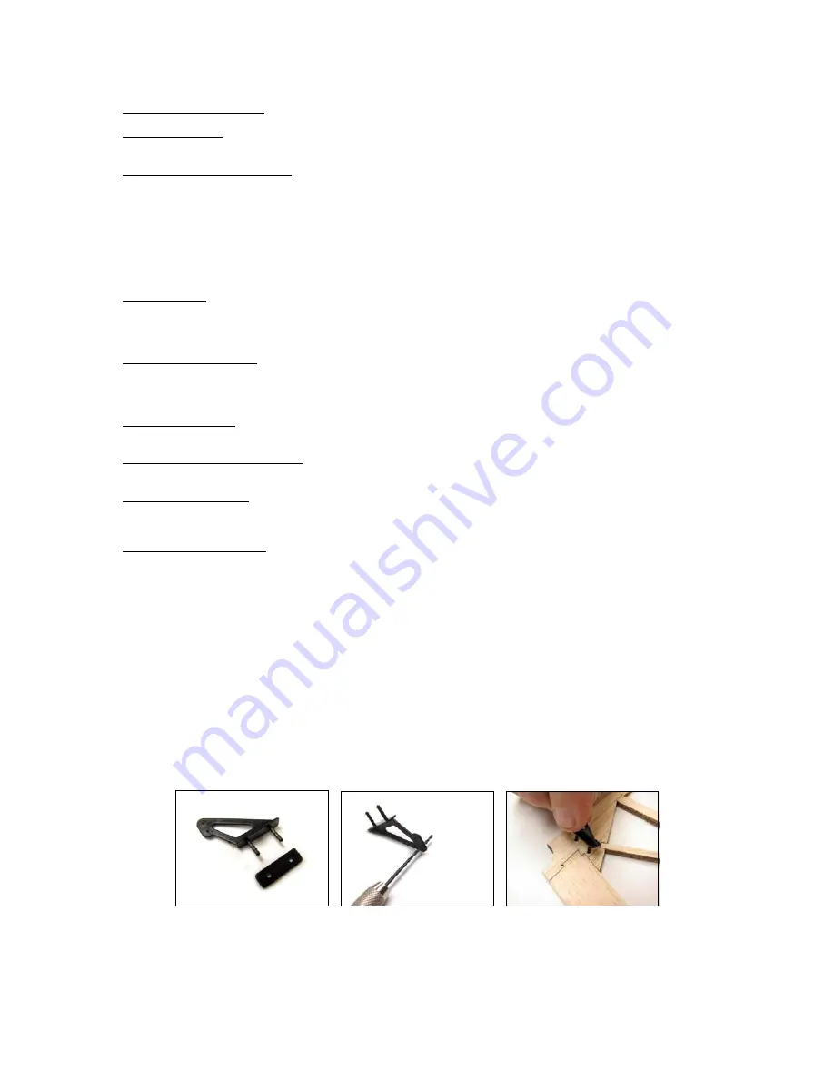
Du-Bro Micro Razor (DUB936) two post control horns have been provided in this kit. Ream the control horns to fit the
.045” wire push rods and Install these on the same side of the control surface that your push-rod will reside on. Control
horns will install into the laser drilled holes in each part. Use the plan sheet as a guide to bend your push/pull rods from
the included 12” and 18” lengths of 0.45” diameter wire stock. Install push/pull rods with the “L” bend placed through the
outer most position on control surface horns and retain using the provided Du-Bro Micro2 EZ-Links (DUB920). In the
photo series below covering and hinges have been omitted for clarity only as this step anticipates that your surfaces are
covered and hinged.


