© 2007 Stevens AeroModel.
Page 14 of 35
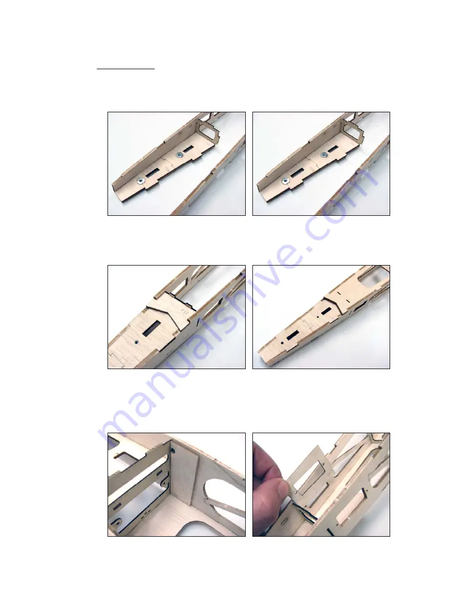
14. Before applying glue locate the 1/16” plywood former F6, and key it to 1/8” balsa former F11, and fuselage
sides, as illustrated below. Square fuselage to building board and tack glue parts into position at tab and notch
locations.
VERY IMPORTANT: The “rim and spike” portion of the blind nut should be located within the
fuselage body (on the same side as the large lightening hole in former F6) so that the threaded portion
of the blind nut is exposed to the underside of the fuselage. Pay close attention to the illustrations
above and below so that you don’t inadvertently install part F11 upside down.
15. Bond 3/32” balsa former F12 to fuselage as illustrated in the first photo below. Next, key 3/32” balsa part F13 to
underside of fuselage atop F12, and spanning fuselage sides, and former F3. Make certain that F13 fits flush
with fuselage sides and is properly seated at all tab and notch locations. Now, square your fuselage assembly
to your flat work surface and tack glue part F13 into position at all tab and notch locations.
16. Before we seal up the aft portion of the fuselage, we have some important business to attend to. First, install
the 3/32” balsa cross-grain doublers F10b within the fuselage assembly, flush with former F3 and F14, as
illustrated in the first photo. *** OPTIONAL AS THE DEFAULT SERVO ARRANGEMENT IS TO USE
PUSHRODS DESCRIBED IN STEPS 23 and 24 Now move aft within the fuselage, and install 1/32” plywood
servo pocket supports SR3 to each side of the assembly (within the fuselage), as illustrated in the second photo
below. ***


