7
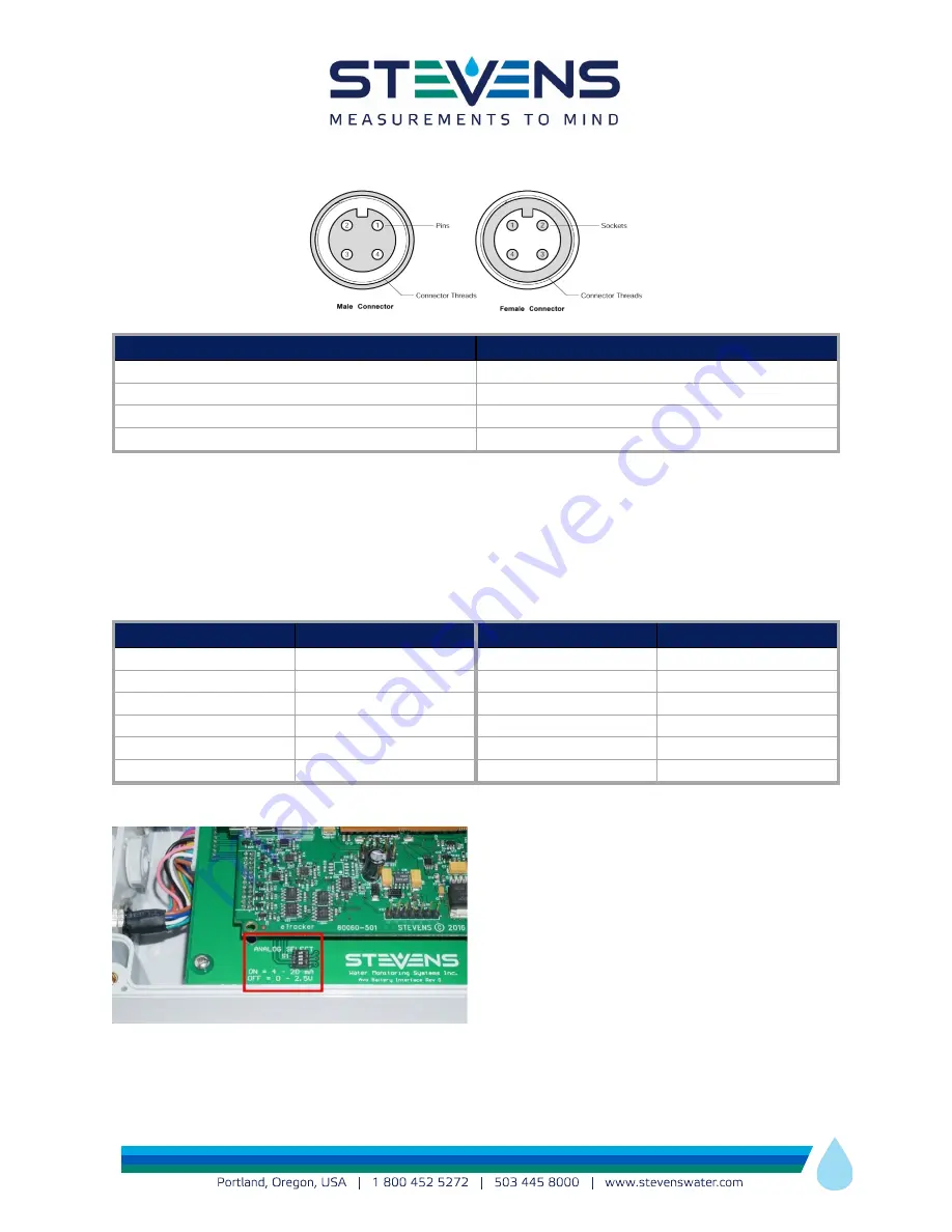
M12 4-Pin Sensor-Side Field-Installable Connector Pinout
Pin Number
Function
1
Power
2
Pulse or Analog (depending on interface)
3
SDI-12 Data
4
GND
Table 2 – Sensor-Side Field-Installable Connector
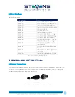
Sensors are not typically connected directly to the 12-Pin SENSOR IN port on Avo. Instead, each Sensor is
first connected to either a multiplexer box or a 1:1 adapter cable. Adapter cables and multiplexer boxes of
different configurations are available from Stevens.
M12 12-Pin SENSORS IN Connector Pinout
Pin Number
Function
Pin Number
Function
1
SENSOR POWER
7
SDI-12 DATA
2
PULSE 1
8
12V Constant
3
No Connect
9
12V Switched
4
Analog 3
10
PULSE 2
5
Analog 2
11
GND
6
Analog 1
12
GND
Table 3 – SENSORS IN Connector Pinout
If 4-20mA sensors are used with Avo then the
appropriate DIP switch must be set to ON for 4 –
20mA current-type sensor. The switch is located on
the top of the battery board. To access, remove all 4
screws from the enclosure and carefully remove the
lid. Failing to select this switch for a 4-20mA sensor
could result in damage to the Avo analog inputs.
The Sensor PWR output is 24V, therefore the
purpose of this switch is to lower the input voltage of the sensor to the analog input range of Avo (0 –


