The motor requires standard AC input (unless an alternate voltage has been
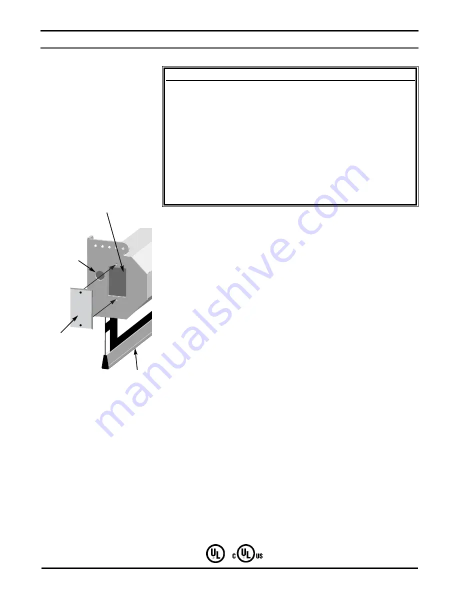
specified). All connections are made to the electrical box on the side of the
unit (audience left).
In addition to the standard high-voltage 3-position switch, there are optional
switch controls available. Follow the inst allation procedure for the type of
switch control you will install.
General suggestions for wiring:
Soldering is recommended.
The use of wire nuts is acceptable.
On models not provided with armored whip, a romex connector
should be installed in the appropriate electrical KO (Knock Out).
Refer to Figure 5 for an illustration of the electrical connection box on the
side of the screen unit.
6
Stewart Filmscreen Corporation
S
TEP
2. E
LECTRICAL
H
OOK
-
UP
Caution
Professional techniques should be used when making any
electrical connection. A qualified electrician should perform
these procedures.
Be sure to follow all standard safety procedures for installing
electrical devices.
Do not disassemble or alter the configuration of the motor or
the unit's electrical connections. This may cause injury to you
or damage to the product.
The electrical connection should be made only to the type of
power source indicated on the marking label.
Figure 5:
Electrical connection
box
Electrical
Connection
Box
Electrical
Knockout
Electrical
Access
Plate
Screen


