12
10
ATTACH 6
WIRES TO
BREAKOUT
BOARD
22nJ
47
n
J
22
n
J
47
n
J
33
n
J
TL072
1uF
10uF
10uF
1uF
1uF
1uF
1uF
08 EDT
10uF
1uF
IN GND SW OUT
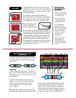
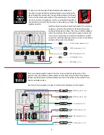
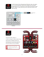
Solder the four wires from
the bottom of the printed
circuit board to eyelets
in the breakout board as
shown.
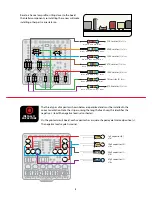
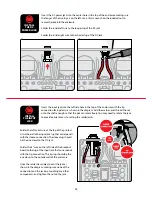
Solder one end of each 4"
wire to the last two eyelets
on the breakout board.
INSTALL
FOOTSWITCH
INTO
BREAKOUT
BOARD
9
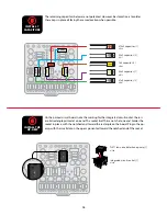
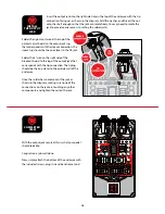
Orient the breakout board with the text facing
up, reading left to right. Slide the lugs of the
footswitch up through the bottom of the board.
If the lugs of the footswitch don’t quite fit in the
breakout board, use a pair of pliers to gently
bend the lugs of the footswitch until the breakout
board slides over the lugs. Solder each lug to the
corresponding breakout board eyelet.
IN GND SW OUT
IN G
ND S
W OU
T
You can use the pedal
enclosure as a mount for
the footswitch while you
solder the breakout board
to it. Just lay the enclosure face-
up and drop the switch in its
hole. No need to fasten it with
a nut from the back if you don’t
want to.


