15
15
INSTALL
THE DC
POWER JACK
INSTALL
THE INPUT
JACK
16
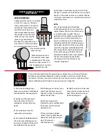
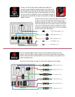
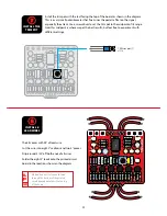
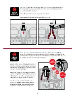
Insert the DC power jack into the center hole in the top of the enclosure making sure
the longer of the two lugs is on the left. Use a 14mm wrench on the included nut to
secure the jack into the enclosure.
Solder the inside left wire to the longer lug of the DC jack.
Solder the inside right wire to the shorter lug of the DC jack.
SLEEVE
SLEEVE
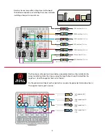
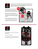
Insert the input jack into the left side hole in the top of the enclosure with the tip
connection facing down, as shown in the diagram. Add the washer, and thread the nut
onto the shaft enough so that the pot can rotate freely. You may need to rotate the jack
to provide easier access to setting the solder joints.
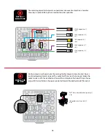
Solder the left-most wire at the top of the printed
circuit board to the input jack lug that corresponds
with the sleeve connection. The sleeve lug should
be the one closer to the DC jack.
Solder the 4" wire on the left side of the breakout
board to the lug of the input jack that corresponds
with the tip connection. The tip lug should be the
one closer to the outside wall of the enclosure.
Once the solder has cooled, orient the jack as
shown in the diagram, making sure none of the
connections on the jack are touching any other
components, and tighten the nut on the jack.


