8
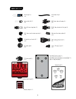
5V6 diode (1)
#7520
1N5817 rectifier diode (1)
#7522
BC549 transistor (5)
#7510
B
C
54
9
C
-J2
3
K
30A
G
R
7L
1N914 diode (3)
#7521
2SK30A transistor (1)
#7517
INSTALL
5 DIODES
AND 6
TRANSISTORS
2
INSTALL 27
RESISTORS
3
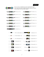
390Ω resistor (1)
#7349
Orange White Black Black Brown
470Ω resistor (1)
#7355
Yellow Violet Black Black Brown
1K resistor (3)
#7357
Brown Black Black Brown Brown
3.3K resistor (1)
#7377
Orange Orange Black Brown Brown
10K resistor (3)
#7362
Brown Black Black Red Brown
4.7K resistor (3)
#7359
Yellow Violet Black Brown Brown
2N5089
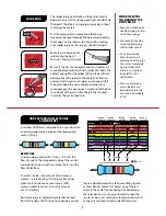
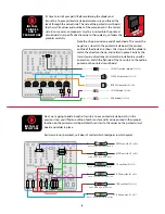
It’s time to install your parts! Before soldering the diodes and
transistors to your printed circuit board, make sure you thread the
leads through the correct side. The side of the printed circuit board
that has white values and outlines of the components is the correct
side. In some cases, components must be inserted into the printed
circuit board in a specific direction due to their polarity, so follow the
graphics carefully.
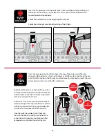
Note the stripe around one end of each diode. This marks the
negative (–) lead. On the printed circuit board, the printed
outline of the diode also shows this stripe. Install the diode to
match the direction shown, and solder in place. Similarly, the
transistors are directional, and must be installed in a specific
orientation. Match the flat side of the transistors to the outline
printed on the printed circuit board.
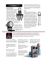
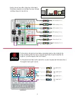
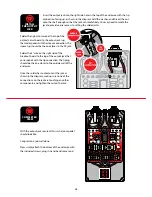
Next, we’re going to add a bunch of resistors to our printed circuit board. As in the
previous step, you’ll find an outline of each resistor and its value printed in their proper
location on the printed circuit board. Match resistors to the values on the printed circuit
board and solder in place.
Resistors are not polarized, so it doesn’t matter which lead goes in which eyelet.


