ENGINE INSTALLATION
Page ENGINE INSTALLATION-4
Z001007/0_4_September 2007
INSTALLATION INSTRUCTION
When assembling a coupling, or a connecting shaft between engine and gear, or when flanging a gear, the end
clearance of the engine's crankshaft must not be affected. V-belts, gear couplings or similar connecting links
thus should permit to be encaged easily. Also when flanging a gear onto the engine, make sure that after
tightening of the fastening screws no axial load or tension is transmitted onto the crankshaft. It is, therefore,
necessary to check the end clearance of the crankshaft journal before and after assembly. During both checks,
the clearance must be equal. The crankshaft must not spring back after pressing it against the front and rear collar
of the lapped bearing.
On boats destined for frequent reversing and maneuvring, e.g. service boats, the couplings are heavily stressed
by start-up impacts and acceleration. For this reason, a larger coupling should be chosen. In addition, it should
be considered not to drive too long at the critical speed range.
If a disconnectable coupling is used, the admissible axial load of the crankshaft must not be exceeded.
5.2.2. Universal-Joint Shafts
Principles:
A universal joint produces a more or less strong irregularity on the driving axle, depending on the diffraction angle.
This irregularity is compensated by providing a second universal joint, under the following conditions:
1. The two forks of the intermediate part must be coplanar.
2. The diffraction angle of the second joint must be of the same size as that of the first one; both joints must
be coplanar.
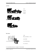
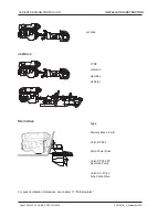
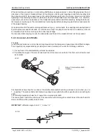
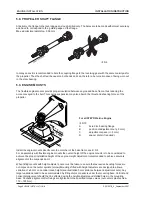
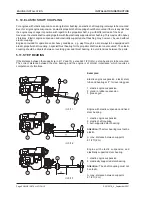
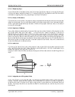
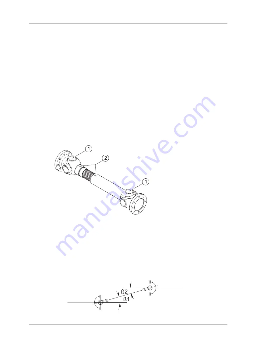
The illustration shows how the two forks of the intermediate shaft should be positioned to each other (acc. to
1. - coplanar). The splined shaft ends mostly show index arrows which should be opposite when connecting the
shaft.
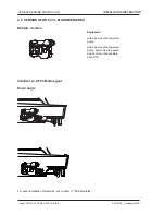
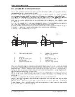
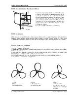
The following illustration shows the Z- layout of a universal-joint shaft.
The two angles ß1 and ß2 must be equal. This means that with Z- design the contact faces of the shaft ends for
drive and drift must be parallel to each other.
IMPORTANT
: diffraction angle ß min = 1°, ß max = 6°
1
forks of intermediate shaft
2
marking
ill. 5/1
ill. 5/2

