FUEL SYSTEM
Page FUEL SYSTEM-6
Z001007/0_4_September 2007
INSTALLATION INSTRUCTION
The air-vent pipe is to be laid from the hightest point of each tank to a protected area on deck. On the upper end
of these pipes a curve of 180° is to be provided which avoids the entering of water into the tanks. The air-vent
pipes should also be arranged in such a way that e.g. flowing out gas cannot be ignited or enter into the rooms
aboard.
The fuel pipes for the engine can be made of seamless, tempered copper tubes or of steel tubes type Bundy tube.
Steel tubes are much stronger than copper tubes, and should, therefore, be used as far as possible.
The hose pipes have to comply with specific conditions of use and respective local waterway regulations (see
hints in the preface).
Specific data for fuel hoses:
synthetic rubber hose with plies of fabric
size DN 8
resistant to Diesel fuel
fire proof
temperature range: -30 bis +30 °C
operating pressure 145 psi (10 bar)
Up to lengths of 2 ft (6 m), outside diameter of the fuel suction pipe should be 3/8" (10mm). A longer suction
pipe will require a larger diameter, e.g. 1/2" (12mm)
From the overflow valve on the engine a fuel return pipe to the tank, or to the daily tank if available, is to be laid.
Min. outside diameter of the fuel return pipe should be 3/8" (10mm).
On the engine side, fuel pipes are always to be installed.
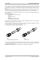
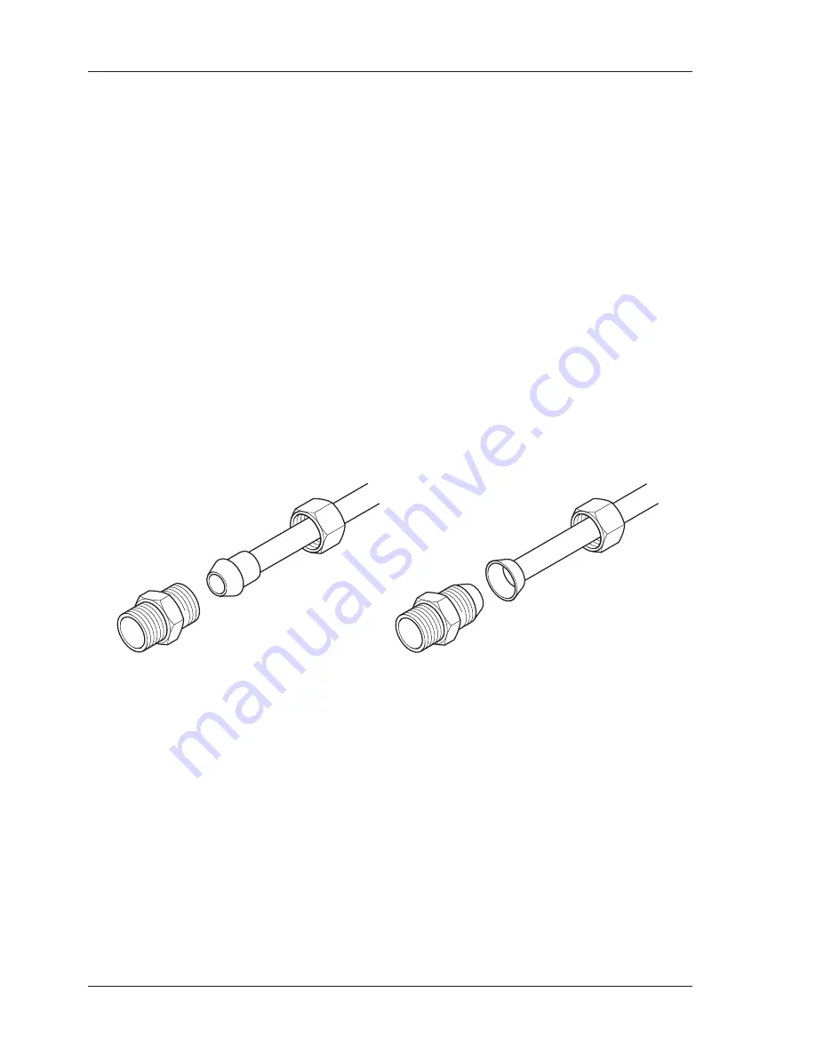
The connections of the fuel pipes are to be flanged with a special tool. Loose or soft soldered tapered pieces
must not be used. When using tapered pieces, these are to be fixed on the pipes by brazing. The best solution
is, however, a flanging of pipes.
Well tighten the fuel pipes on planks or rigid supports, to avoid vibrations or pipe fracture.
ill.7/4
fuel pipe with brazed tapered piece
ill.7/5
flanged fuel pipe

