Engine
67/87
Z001138-1_2013-02-01
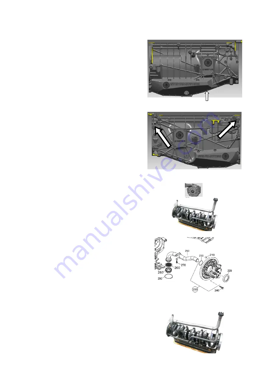
13. First loosen 16 allen head screws SW 5,
then 7 hexagon screws SW15
14. Force apart housing half’s and remove.
Assembly
1. Check membranes of frame sealing and
rubber pads for damage, replace if
necessary.
2. Clean and degrease all sealing surfaces.
3. Clean sealing profiles from adhesive
residues.
4. Apply front and rear ring carrier with
construction adhesive
LOCTITE 620
, in
the area of the parting plane from the
engine housing. Wet sealing surfaces of
screws with surface sealing agent
LOCTITE 5182
.
5. First put suction-sides housing half onto
dowel pin, and then check for second
housing half whether oil suction pipe and
oil suction pipe horn do not collide with the
housing. Screw together the housing
halves.
Summary of Contents for Marine Engine 2012 Series
Page 35: ...General 35 65 Z001138 1_2013 02 01 Trouble Indication ...
Page 36: ...General Preliminary Service Manual MARINE 2012 Z001138 1_2013 02 01 36 65 ...
Page 51: ...General 51 65 Z001138 1_2013 02 01 G Notes on safety ...
Page 69: ...Engine Z001138 1_2013 02 01 4 87 Kapitel MOUNT BRACKET COVER T BELT GASKET SET ...
Page 154: ...Fuel System Z001138 1_2013 02 01 2 51 ...
Page 159: ...Fuel System 7 51 Z001138 1_2013 02 01 03 00 03 Unit injector ...
Page 190: ...Fuel System Z001138 1_2013 02 01 38 51 Schema Injection Timing Device ITD ...
Page 211: ...Cooling System 5 21 Z001138 1_2013 02 01 ...
Page 231: ...Electrical System Z001138 1_2013 02 01 4 47 ...
Page 235: ...Electrical System Z001138 1_2013 02 01 8 47 ...
Page 236: ...Electrical System 9 47 Z001138 1_2013 02 01 ...
Page 238: ...Electrical System 11 47 Z001138 1_2013 02 01 ...


