Fuel System
Z001138-1_2013-02-01
24/51
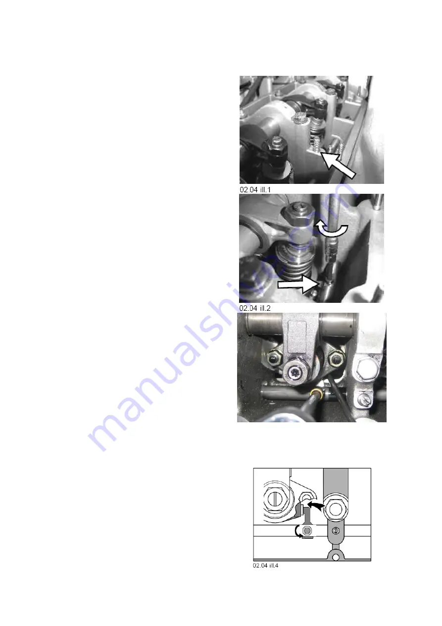
03.02.04 Adjust
control
link (injection quantity)
Prior to adjustment, unit injector must be
tightened properly, and control rack must
be fixed in position with set pin. (refer
03.02.03)
NOTE:
Readjust all control links even if only
one link has been opened.
STARTING POSITION:
Slacken
left-handed
setscrew of control link
(use special tool P/N 2300908/0). Turn
control link against bulkhead on camshaft
housing.
1. Carefully position end of control link on
front side of unit injector quantity control
gear (preferably use small screwdriver).
2. Turn control link against unit injector
quantity control gear until control gear
completely pushes against upper
calibrated stop and hold position with
screwdriver. Remain in this position and
tighten
left-hand-thread
screw of control
link as specified with a torque of
7 Nm +/-1.
Repeat steps 1 and 2 for the rest of unit
injectors to obtain proper setting of the
control rack.
3. Calibrate rack position, refer to 06.10.02
4. Release fixing of control rack, refer to
03.02.05
Summary of Contents for Marine Engine 2012 Series
Page 35: ...General 35 65 Z001138 1_2013 02 01 Trouble Indication ...
Page 36: ...General Preliminary Service Manual MARINE 2012 Z001138 1_2013 02 01 36 65 ...
Page 51: ...General 51 65 Z001138 1_2013 02 01 G Notes on safety ...
Page 69: ...Engine Z001138 1_2013 02 01 4 87 Kapitel MOUNT BRACKET COVER T BELT GASKET SET ...
Page 154: ...Fuel System Z001138 1_2013 02 01 2 51 ...
Page 159: ...Fuel System 7 51 Z001138 1_2013 02 01 03 00 03 Unit injector ...
Page 190: ...Fuel System Z001138 1_2013 02 01 38 51 Schema Injection Timing Device ITD ...
Page 211: ...Cooling System 5 21 Z001138 1_2013 02 01 ...
Page 231: ...Electrical System Z001138 1_2013 02 01 4 47 ...
Page 235: ...Electrical System Z001138 1_2013 02 01 8 47 ...
Page 236: ...Electrical System 9 47 Z001138 1_2013 02 01 ...
Page 238: ...Electrical System 11 47 Z001138 1_2013 02 01 ...


