Fuel System
Z001138-1_2013-02-01
44/51
03.11 Replace Glow Plug
Preparation:
for glow plug of first cylinder, remove control solenoid - refer to
03.08.01
for glow plug of second to sixth cylinder, remove intake manifold -
refer to 01.08.01
Disconnect battery.
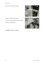
1. Remove connector from glow plug.
2. Unscrew glow plug(s) with special
tool No. VR00146/0.
3. Screw in new glow plug(s) by
means of special tool No.
VR00146/0 and tighten by means
of special tool No. 2300703/0 with
a torque of
15 +/-1 Nm
.
NOTE:
Grease thread of glow plug
with high temperature grease (PN
Z012222-0).
NOTE:
Exactly keep torque of
15 +/-
1Nm
when fixing glow plugs!
Further assembly is done in reverse
order of disassembly.
Summary of Contents for Marine Engine 2012 Series
Page 35: ...General 35 65 Z001138 1_2013 02 01 Trouble Indication ...
Page 36: ...General Preliminary Service Manual MARINE 2012 Z001138 1_2013 02 01 36 65 ...
Page 51: ...General 51 65 Z001138 1_2013 02 01 G Notes on safety ...
Page 69: ...Engine Z001138 1_2013 02 01 4 87 Kapitel MOUNT BRACKET COVER T BELT GASKET SET ...
Page 154: ...Fuel System Z001138 1_2013 02 01 2 51 ...
Page 159: ...Fuel System 7 51 Z001138 1_2013 02 01 03 00 03 Unit injector ...
Page 190: ...Fuel System Z001138 1_2013 02 01 38 51 Schema Injection Timing Device ITD ...
Page 211: ...Cooling System 5 21 Z001138 1_2013 02 01 ...
Page 231: ...Electrical System Z001138 1_2013 02 01 4 47 ...
Page 235: ...Electrical System Z001138 1_2013 02 01 8 47 ...
Page 236: ...Electrical System 9 47 Z001138 1_2013 02 01 ...
Page 238: ...Electrical System 11 47 Z001138 1_2013 02 01 ...


