General
Preliminary
Service Manual MARINE 2012
Z001138-1_2013-02-01
40/65
Engine Break-In procedure
The following procedure must be used on new and rebuilt STEYR Diesel Engines. You
must follow the Engine Break-In instructions during the first 20 running hours to ensure
maximum performance and longest engine life.
NOTE: NONOBSERVANCE OF BREAK-IN INSTRUCTIONS MAY CAUSE SEVERE
ENGINE FAILURE.
First Two Hours
For the first five to ten minutes of operation, run engine at a fast idle (below 1500 RPM).
For the remaining first two hours of operation.
During this period, vary the engine speed frequently by accelerating to approximately
three-fourth throttle for two to three minutes, then speed remain at cruising engine
operating temperature, alternate engine speed, while driving, to assist the break-in of rings
and bearings.
NOTE: DO NOT RUN ENGINE AT A CONSTANT RPM FOR LONGER PERIODS
DURING THIS INITIAL TWO HOURS OF BREAK-IN.
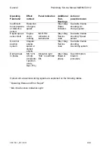
Attention:
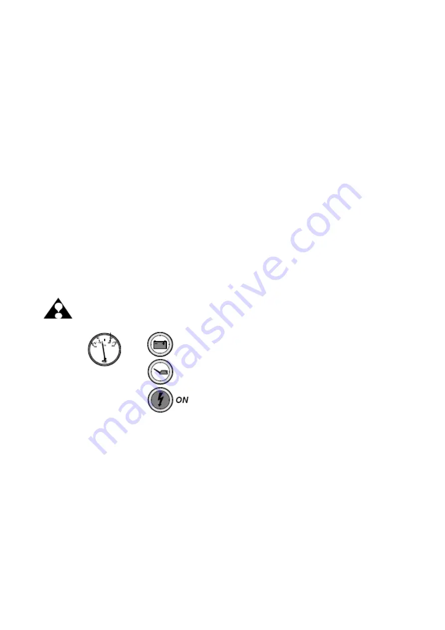
Warning indication engine over load during break - in via ECU
The ECU controls during the first two hours of engine operation the load on the
engine and alarms the drive by the "Check Engine Light", if much power is
demanded from the new engine.
Illustration represents an example
which may differ from the installation in
a vehicle.
In case the operator get alert, when running the engine during break in phase,
by this "Break - In" warning indication (CEL light - ON), the throttle position
must be reduced until this signal extinguish.
Next Eight Hours
For the next eight hours, continue to run engine at approximately three-fourth throttle or
less.
Occasionally reduce throttle to lower loads and let engine temperature cool down. During
this eight hours of running it is permissible to run at full throttle for periods of less than two
minutes.
NOTE: DURING BREAK-IN, DO NOT RUN ENGINE AT A CONSTANT RPM
FOR LONGER PERIODS.
Summary of Contents for Marine Engine 2012 Series
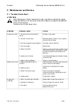
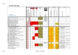
Page 35: ...General 35 65 Z001138 1_2013 02 01 Trouble Indication ...
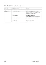
Page 36: ...General Preliminary Service Manual MARINE 2012 Z001138 1_2013 02 01 36 65 ...
Page 51: ...General 51 65 Z001138 1_2013 02 01 G Notes on safety ...
Page 69: ...Engine Z001138 1_2013 02 01 4 87 Kapitel MOUNT BRACKET COVER T BELT GASKET SET ...
Page 154: ...Fuel System Z001138 1_2013 02 01 2 51 ...
Page 159: ...Fuel System 7 51 Z001138 1_2013 02 01 03 00 03 Unit injector ...
Page 190: ...Fuel System Z001138 1_2013 02 01 38 51 Schema Injection Timing Device ITD ...
Page 211: ...Cooling System 5 21 Z001138 1_2013 02 01 ...
Page 231: ...Electrical System Z001138 1_2013 02 01 4 47 ...
Page 235: ...Electrical System Z001138 1_2013 02 01 8 47 ...
Page 236: ...Electrical System 9 47 Z001138 1_2013 02 01 ...
Page 238: ...Electrical System 11 47 Z001138 1_2013 02 01 ...

