Engine
27/87
Z001138-1_2013-02-01
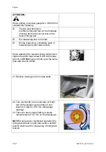
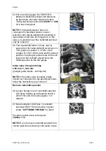
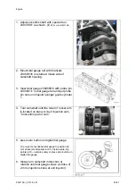
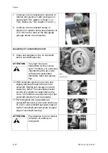
(cylinder 1; at TDC ) with locking pin in fly
wheel bore). See chapter 01.00.01. With
locked crankshaft, the plunger guide stroke
of unit injector at first cylinder should show
the following dial gauge value:
Index value
of engine timing 3,59 mm +/- 0,04 mm
(plunger guide stroke - unit injector)
NOTE:
If the index value of engine timing
should not correspond to the allowed value,
follow the instructions as per item 25.
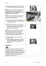
33. In case of correct index value of engine
timing, remove locking pin on crankshaft
and tighten hexagon nut of camshaft
sprocket SW 30 with
240 +/-12 Nm
by
holding up with special tool No.2300711/0.
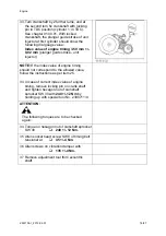
34.
ATTENTION:
The following torques are
to be checked again:
1. Torque on hexagon nut of camshaft
sprocket SW 30
q 240 +/-12 Nm.
2. Fillister socket head screw SW 8 of timing
belt tensioner at
q 45 +/-4 Nm.
3 Allen screws on vibration damper with
q
135
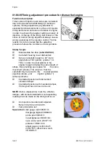
+/-4
Nm.
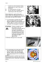
35 Remove adjustment tool 2300736/1 from
eccentric shaft.
36 Reassemble opened components for service
purpose in reverse order
37 Reassemble fan drive (refer to 05.05.02)
Summary of Contents for Marine Engine 2012 Series
Page 35: ...General 35 65 Z001138 1_2013 02 01 Trouble Indication ...
Page 36: ...General Preliminary Service Manual MARINE 2012 Z001138 1_2013 02 01 36 65 ...
Page 51: ...General 51 65 Z001138 1_2013 02 01 G Notes on safety ...
Page 69: ...Engine Z001138 1_2013 02 01 4 87 Kapitel MOUNT BRACKET COVER T BELT GASKET SET ...
Page 154: ...Fuel System Z001138 1_2013 02 01 2 51 ...
Page 159: ...Fuel System 7 51 Z001138 1_2013 02 01 03 00 03 Unit injector ...
Page 190: ...Fuel System Z001138 1_2013 02 01 38 51 Schema Injection Timing Device ITD ...
Page 211: ...Cooling System 5 21 Z001138 1_2013 02 01 ...
Page 231: ...Electrical System Z001138 1_2013 02 01 4 47 ...
Page 235: ...Electrical System Z001138 1_2013 02 01 8 47 ...
Page 236: ...Electrical System 9 47 Z001138 1_2013 02 01 ...
Page 238: ...Electrical System 11 47 Z001138 1_2013 02 01 ...

