48
11
06012
A
12
06010
B
15
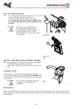
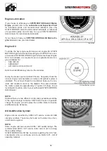
Inversion Switch (optional)
13
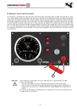
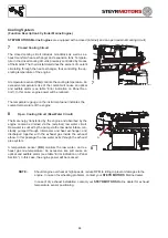
The inversion switch
(A)
which is actuated in case of an incli-
nation of the boat in any direction over 70 °.
Via the main circuit relay the engine is shut down.
For safe guarding reasons the inversion switch must
be checked according to the Service and Maintenance
Schedule.
CAUTION:
After such an event, this temporarily
stored operating condition is to be
cancelled from the engine management
system by ignition “OFF” = “Reset”.
Without “Reset”, a new start of the engine
is not possible.
Interrupt crankshaft housing ventilation (optional)
15
During possible vessel inversion, the by-pass valve
(B)
for
crankshaft housing ventilation is closed too.
This avoids a possible oil outlet via suction through the air
filter.
Instrument Panel
The engines are supplied with the standard instrument panel.
The respective customer may use a self-adapted
STEYR MOTORS
instrument panel or one which corresponds to his own ideas and
requirements.
CAUTION:
For not approved alterations which lead
to engine failure, no liability can be
undertaken.
Dry Operation
After a dry operation of the engine (without raw water cooling), check the impeller of the raw water pump for dam-
ages. Replace if necessary. Grease the impeller, use grease from genuine impeller service kit (see adequate spare
parts catalogue).
13
Series MO
Series SE
A
Summary of Contents for MO114K33
Page 2: ...This Page is intentionaly blank ...
Page 5: ...5 This page is intentionaly blank ...
Page 6: ...6 SAFETY PRECAUTIONS Safety Precautions 7 Introduction 7 ...
Page 21: ...21 This page is intentionaly blank ...
Page 49: ...49 This Page is intentionaly blank ...
Page 91: ...91 Wiring diagram MO 12 V 4 cyl from engine s n 482330250 ...
Page 92: ...92 Wiring diagram MO 24 V 4 cyl from engine s n 482330250 ...
Page 93: ...93 Wiring diagram MO 12 V 2 pol 4 cyl from engine s n 482330250 ...
Page 94: ...94 Wiring diagram MO 24 V 2 pol 4 cyl from engine s n 482330250 ...
Page 95: ...95 Wiring diagram MO E Box external 4 cyl from engine s n 482330250 ...
Page 96: ...96 Wiring diagram MO E Box external 2 pol 4 cyl from engine s n 482330250 ...
Page 101: ...101 Wiring diagram SE E Box 12V 6 cyl ...
Page 102: ...102 SE Series Wiring diagram SE E Box 24V 6 cyl ...
Page 103: ...103 SE Series Wiring diagram external SE E Box 6 cyl ...
Page 104: ...104 Wiring diagram SE E Box 12 V 4 cyl ...
Page 105: ...105 Wiring diagram external SE E Box 12 V 4 cyl ...
Page 106: ...106 Wiring diagram Instument CAN Panel 12 24V ...
Page 107: ...107 Wiring diagram Instument CAN Panel Solas 12 24V ...

